Abstract

Solutions for Low Pressure – Key Points

Why it matters:

Hydraulic control valves rely on pressure differentials to operate. When pressure is too low, standard valves may fail to open or close properly, risking system malfunction.

Common low-pressure scenarios:

  • Elevated tanks and reservoirs.
  • Tank discharge valves with low water levels.
  • Remote terminal points in large distribution systems.

Key solutions:

  • Downstream orifice to create back-pressure – simple, no power required.
  • Low-pressure diaphragm (for use with a DOROT S100 valve) – retrofittable, cost-effective.
  • External, pressurized media – the valve can be controlled by implementing one of the following solutions:
  • Spring removal – requires an external pressure source.
  • Spring-assisted (30NO) or VAC systems – for zero-pressure opening.
  • Double-chamber – for use where technical specifications require, or where there is a need for a fast reaction.
  • Bladder tank – where pressure conditions are intermittent, higher pressure can be stored in a bladder tank for use at times when pressure drops, as an effective alternative to installing an external media source.

Selection criteria:

  • The appropriate solution for any given environment will depend on pressure availability, system complexity, and control requirements.
  • Start with simple mechanical options before considering powered systems.
  • For a quick selection guide, “Solution Selection Guide”.

Got any questions?

Contact Aquestia’s Applications Engineers, who are ready to assist you.

Introduction

Hydraulic control valves (HCVs) operate by harnessing inline pressure as an energy source to manipulate the valve mechanism to open and close. Acting on the surface area of the internal mechanism, the pressure produces a force (following Pascal’s Law: Force = Pressure × Area) that translates into a movement of the internal trim.

The operation of these valves relies on sufficient pressure differentials to generate the forces necessary to overcome resistive forces such as friction, the weight of the mechanism, spring force etc. In standard conditions, the line pressure is sufficient to operate the valve effectively. However, when system pressure falls below minimum thresholds, the standard valve configurations may not function properly, as the available force may not be sufficient to overcome internal resistance.

There are several scenarios in which low-pressure conditions may occur, for example at elevated installations, such as hilltop reservoirs, where static head is naturally low and the dynamic head is even lower, or at the discharge point of a tank, where only the hydrostatic pressure of the water level above the outlet point is available. Such conditions require specialized approaches to ensure reliable valve operation.

This document outlines various solutions for operating hydraulic control valves in such low-pressure conditions, their implementation requirements, and selection criteria.

Understanding Low Pressure Requirements

Definition of “Low” Pressure

Two critical pressure-related parameters affect valve operation:

  • Minimum Operating Pressure: The absolute pressure required at the valve inlet to generate sufficient force to fully open the valve.
  • Minimum Pressure Differential: The difference between upstream and downstream pressures needed to overcome internal resistance and close a fully-open valve.

The table below compares minimum pressure requirements across DOROT valve models and typical competitor products:

Optimizing Hydraulic Control Valves for Extreme Low Pressure

When system pressure falls below these thresholds, valve functionality may be compromised.

Typical Low-Pressure Applications

Low-pressure conditions commonly arise in the following scenarios:

  1. Tank and Reservoir Level Control – when level control valves are used to fill tanks or reservoirs situated at elevated locations, such as a hill top, the elevation difference naturally reduces available pressure head, while friction losses due to high demand through long supply lines further diminish inlet pressure.
  2. Tank Discharge Applications – valves at the tank discharge point rely solely on the hydrostatic upstream pressure from the water level above them. For low-elevation tanks, or as the water level in the tank decreases, available pressure drops proportionally.
  3. Remote Distribution Networks – terminal points in lengthy distribution networks may experience significant pressure reduction due to pipe friction losses.
Optimizing Hydraulic Control Valves for Extreme Low Pressure

* HGL: Hydraulic Grade Line – the line representing the available head (sum of the pressure and elevation) at any point in the system

Low-Pressure Solutions

Addition of Downstream Resistance

Technical Principle: Adding a downstream orifice plate or similar restriction creates back pressure that increases the opening force by allowing downstream pressure to act on the valve’s internal trim. Additionally, the restriction reduces flow rate, which minimizes pressure losses in the supply system and consequently increases the available inlet pressure.

Implementation Requirements:

  • Ensure the orifice plate is sized according to flow requirements (preferably one that produces >2mwc at the required flow rate).
  • Install the orifice plate downstream of the valve. For tank/reservoir-filling valves, the best location is at the outlet of the pipe into the tank or reservoir. In other cases, the orifice plate can be located between the flanges on the downstream side of the valve.
  • Verify sufficient clearance for maintenance access.

Benefits:

  • Simple implementation.
  • Low cost (relative cost index: 2/5).
  • Minimal maintenance requirements (complexity index: 1/5).
  • No external power sources needed.

Notes:

  • This method increases the resistance, i.e. adds pressure losses to the system, and reduces the maximum flow capacity under high demand.
  • It is less effective in systems with widely varying flow requirements.

Optimizing Hydraulic Control Valves for Extreme Low Pressure


Low-Pressure Diaphragm Solutions

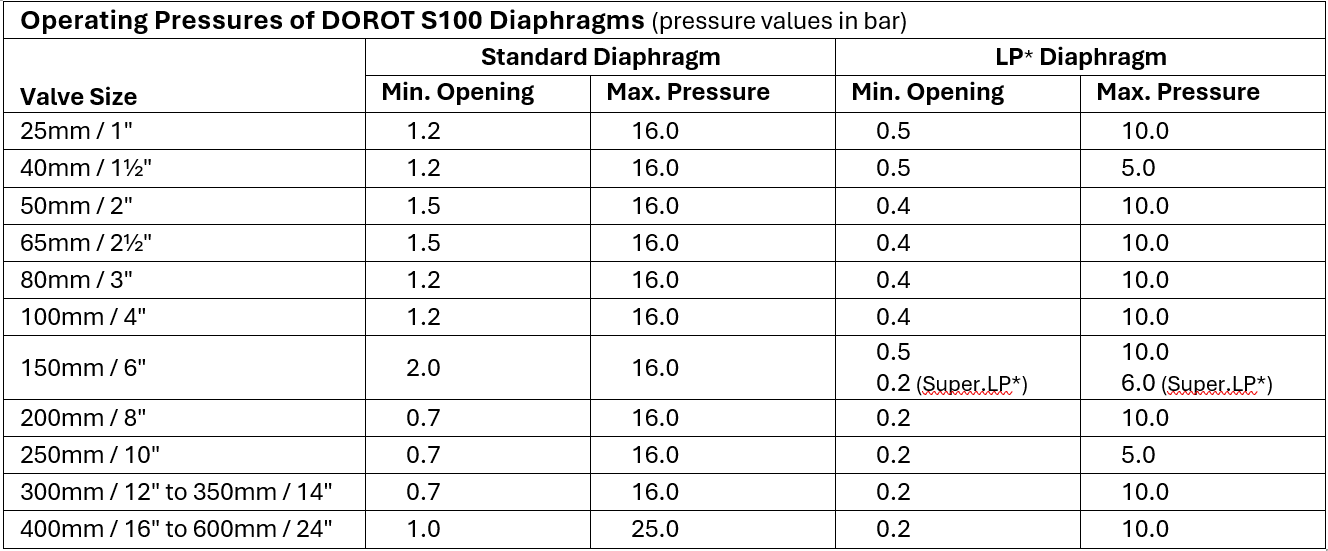
For DOROT S100 valves, replacing the standard diaphragm with a low-pressure (LP) diaphragm can significantly reduce the minimum pressure required for proper operation.

Benefits:

  • Ideal for DOROT S100 valves (direct sealing diaphragm, weir type valves).
  • Simple retrofit to existing installations of the same valve model.
  • Cost-effective alternative to more complex solutions (relative cost index: 1/5).
  • Low maintenance complexity (index: 1/5).

Notes:

  • Low-pressure (LP) diaphragms in valves that may experience moderate or high differential pressures are not recommended for regulation applications (e.g., pressure or flow control), as they can become unstable—exhibiting chattering and vibration under such conditions.
  • The maximal operating pressure of a valve that has an LP diaphragm is lower than the standard configuration. (Please refer to DOROT S100 publications for technical specifications.)
  • Ideally, the LP diaphragm should be combined with a downstream orifice (even if doing so produces a ΔP as low as 1 mwc), to achieve optimal performance.
Optimizing Hydraulic Control Valves for Extreme Low Pressure

* Note: LP = Low Pressure; Super.LP = Super Low-Pressure diaphragm option.

External Media Solutions

When line pressure is insufficient for valve operation, external pressurized media, such as compressed air or water, can be used to force open the valve. To use this option, the valve and/or the control-trim design needs to be modified to one of the following options:

  • Spring Removal:

The spring is removed from the control chamber of a standard control valve, eliminating the downward spring force which resists the opening, thereby enabling full opening of the valve at lower pressures. External control pressure, somewhat higher than the inline pressure, must be applied to ensure valve closure in the absence of the closure-assisting spring.

Benefits:

  • Enables DOROT S300 and DOROT S500 valves to operate at pressures as low as 0.2 bar.
  • Enables DOROT S100 valves with LP diaphragms to operate with inline pressure as low as 0.1 bar.
  • Simple retrofit to existing installations.
  • Cost-effective alternative to more complex solutions (relative cost index: 2/5).
  • Low maintenance complexity of 2/5.

Notes:

  • External media pressure requirement: at least 0.5 bar higher than maximum inline pressure.
  • For DOROT S100 valves, external pressure should not exceed inline pressure by more than 1.5 bar.
  • The control-loop must vent the control-chamber to atmospheric pressure (use 3-way control).
  • Ideally, the spring-removal solution should be combined with a downstream orifice (even if that produces a ΔP as low as 1 mwc), to achieve optimal performance.

Optimizing Hydraulic Control Valves for Extreme Low Pressure

This single-chamber valve, is held in the open position by an external spring. The valve remains open unless actively commanded to close. Closure requires a high enough external pressure-source to overcome both the spring force and the internal opening force.

Benefits:

  • Normally-open configuration (fully-open even at zero inline pressure).
  • Minimal internal dynamic sealing and high long-term reliability.
  • Maintenance complexity index: 3/5.
  • Relative cost index: 4/5.

Notes:

  • The external control media is required to be at a pressure that is at least 0.8 bar higher than maximal inline pressure.
  • An additional 50cm clearance is needed above the valve for spring assembly.

Optimizing Hydraulic Control Valves for Extreme Low Pressure

VAC Control Loop Systems

The control valve is forced to open by a vacuum that is generated via a flow-driven device (ejector, Venturi or vacuum pump). External pressure is used to generate sub-atmospheric pressure above the diaphragm, pulling the trim open even at zero inline pressure, and redirecting the external pressure into the chamber closes the valve.

Benefits:

  • A suction effect pulls the internal trim to the open position, even at ‘zero’ pressure.
  • When controlled to close, the operation is reversed by admitting the control pressure into the control chamber.
  • Applicable to virtually any valve type.
  • Requires very little or no modification to the valve structure and design (spring is normally removed). 
  • In some cases, the system can be used for modulating/regulating functions.
  • Relative cost index: 4/5.
  • Maintenance complexity index: 3/5.

Notes:

  • This solution requires some expertise in control loop design to divert the pressure of the external media through the vacuum-emitting device or redirect it into the control chamber of the valve, to open and to close the control valve.
  • The control loop design should account for sufficient pressure supply to drive the required sub-atmospheric pressure valve. In the case of DOROT S100 valves, the maximal closing pressure must be limited to P ≤ maximal inline pressure plus 1.5  bar. Example: if the maximal inline pressure is 2 bar, the control pressure must be 2 ≤ P ≤ 3.5 bar.
  • In most cases, it is recommended to remove the internal spring. Here, the control pressure must be higher than the maximal inline pressure plus  0.5 bar. In the above example, this would be 2.5 ≤ P ≤ 3.5 bar.
  • For DOROT S100 valves, it is recommended to use a low-pressure diaphragm.


Optimizing Hydraulic Control Valves for Extreme Low Pressure


Double-Chamber Configurations with 4-Way Control

Here, a double-chamber version of the DOROT S300 valve is implemented, by inserting a separation disc between the diaphragm and the sealing plug. This forms a second control chamber below the diaphragm, into which external control pressure can be applied to force the internal trim upwards while the top control chamber is de-pressurized. Venting the lower control chamber and pressurizing the top one forces the valve into a drip-tight closed position.

Benefits:

  • Utilizes DOROT S300 models 30D, 31D, or 32D.
  • A patented design enables the conversion of a standard single-chambered valve into a double-chambered design with a simple separation disc addition, requiring no other parts to be replaced.
  • Fully-open position, even with zero inline pressure.
  • Relative cost index: 5/5.
  • Maintenance complexity index: 5/5.

Notes:

  • Any double-chamber valve design of any make requires the shaft to move through internal dynamic seals. The additional friction and seal wear and tear reduces the reliability of the basic valve.
  • Care should be taken to avoid water hammer due to the potentially rapid closure speed.
  • Requires a 4/2 or dual 3/2 control devices. Optional control may be designed more simply, depending on site conditions.

Optimizing Hydraulic Control Valves for Extreme Low Pressure


When External Pressurized Control Media is Unavailable – an Optional Solution:

Where low-pressure conditions are intermittent, a bladder tank with a non-return valve can store higher pressure from the system during normal-pressure operation. This stored pressure can later be used to operate the valve when low-pressure conditions exist.

Optimizing Hydraulic Control Valves for Extreme Low Pressure

Solution Selection Guide

Comparison Matrix

Optimizing Hydraulic Control Valves for Extreme Low Pressure

Optimizing Hydraulic Control Valves for Extreme Low Pressure

(*) Note: External media system costs are not included in the above relative cost ratings, and may vary significantly depending on whether suitable pressure sources already exist on site.


Selection Methodology

Selection of the most appropriate low-pressure solution should follow these prioritized criteria:

  1. Performance requirements: Select a solution that enables operation at pressures lower than the minimum expected at the valve inlet.
  2. Simplicity and reliability: Preference should be given to simpler solutions that minimize potential points of failure.
  3. Cost efficiency: Consider both initial implementation and long-term operational costs.
  4. Compliance: Ensure that the solution meets customer-specifications and site requirements.

How to Choose the Right Solution

First, determine the minimum expected line pressure at the valve location. Then take the relevant course of action from the list below:

  1. Pressure is only marginally below standard operating requirements, consider:
    • Adding a downstream orifice plate (the simplest solution), and/or
    • Installing a L.P diaphragm for DOROT S100 valves
  2. Pressure is significantly below standard requirements, consider:
    • Spring removal with an external pressure source (if available), or
    • Spring-assisted opening (30NO), or
    • VAC control loop (for moderately complex installations).
  3. Zero or near-zero pressure applications, implement:
    • Spring-assisted opening (30NO), or
    • VAC control loop for moderately complex installations, or
    • Double-chamber configuration (for critical applications).
  4. Pressure drops below minimal value intermittently – consider deploying a bladder tank as a temporary pressure-accumulator for use during low-pressure conditions.

Optimizing Hydraulic Control Valves for Extreme Low Pressure

Important Note: Compare actual and designed pressure conditions to the specific valve in use. It is malpractice to require special and non-standard low-pressure valve configuration when simpler solutions may suffice. Always consult Aquestia technical support when conditions appear to require complex solutions, as DOROT valves often offer wider operating ranges than competitor products.

Conclusion

Hydraulic control valves can be successfully deployed in low-pressure environments, with appropriate adaptation. The range of solutions presented in this guide allows for customized approaches based on site conditions, available resources, and operational requirements.

Aquestia valves offer superior low-pressure capabilities compared to the market benchmark, with the DOROT S300 and DOROT S500 series operable at pressures as low as 0.2 bar with simple modifications, and effectively zero pressure through use of appropriate control systems.