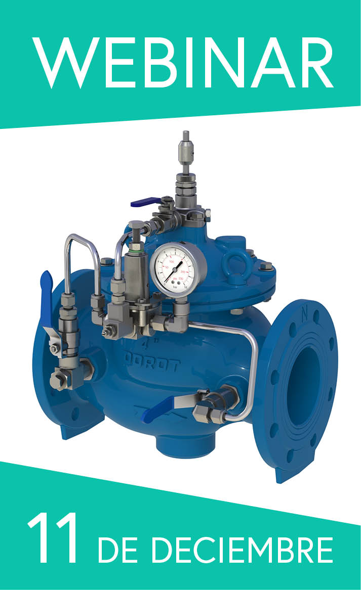
Join Our Pressure Reducing Valves Webinar
Explore how PRVs operate, where they deliver the greatest benefits, and how to select and adjust the right model for each hydraulic scenario
Why it matters:
Hydraulic control valves rely on pressure differentials to operate. When pressure is too low, standard valves may fail to open or close properly, risking system malfunction.
Common low-pressure scenarios:
Key solutions:
Selection criteria:
Contact Aquestia’s Applications Engineers, who are ready to assist you.
Hydraulic control valves (HCVs) operate by harnessing inline pressure as an energy source to manipulate the valve mechanism to open and close. Acting on the surface area of the internal mechanism, the pressure produces a force (following Pascal’s Law: Force = Pressure × Area) that translates into a movement of the internal trim.
The operation of these valves relies on sufficient pressure differentials to generate the forces necessary to overcome resistive forces such as friction, the weight of the mechanism, spring force etc. In standard conditions, the line pressure is sufficient to operate the valve effectively. However, when system pressure falls below minimum thresholds, the standard valve configurations may not function properly, as the available force may not be sufficient to overcome internal resistance.
There are several scenarios in which low-pressure conditions may occur, for example at elevated installations, such as hilltop reservoirs, where static head is naturally low and the dynamic head is even lower, or at the discharge point of a tank, where only the hydrostatic pressure of the water level above the outlet point is available. Such conditions require specialized approaches to ensure reliable valve operation.
This document outlines various solutions for operating hydraulic control valves in such low-pressure conditions, their implementation requirements, and selection criteria.
Two critical pressure-related parameters affect valve operation:
The table below compares minimum pressure requirements across DOROT valve models and typical competitor products:
When system pressure falls below these thresholds, valve functionality may be compromised.
Low-pressure conditions commonly arise in the following scenarios:

* HGL: Hydraulic Grade Line - the line representing the available head (sum of the pressure and elevation) at any point in the system
Technical Principle: Adding a downstream orifice plate or similar restriction creates back pressure that increases the opening force by allowing downstream pressure to act on the valve’s internal trim. Additionally, the restriction reduces flow rate, which minimizes pressure losses in the supply system and consequently increases the available inlet pressure.
Implementation Requirements:
Benefits:
⚠ Notes:
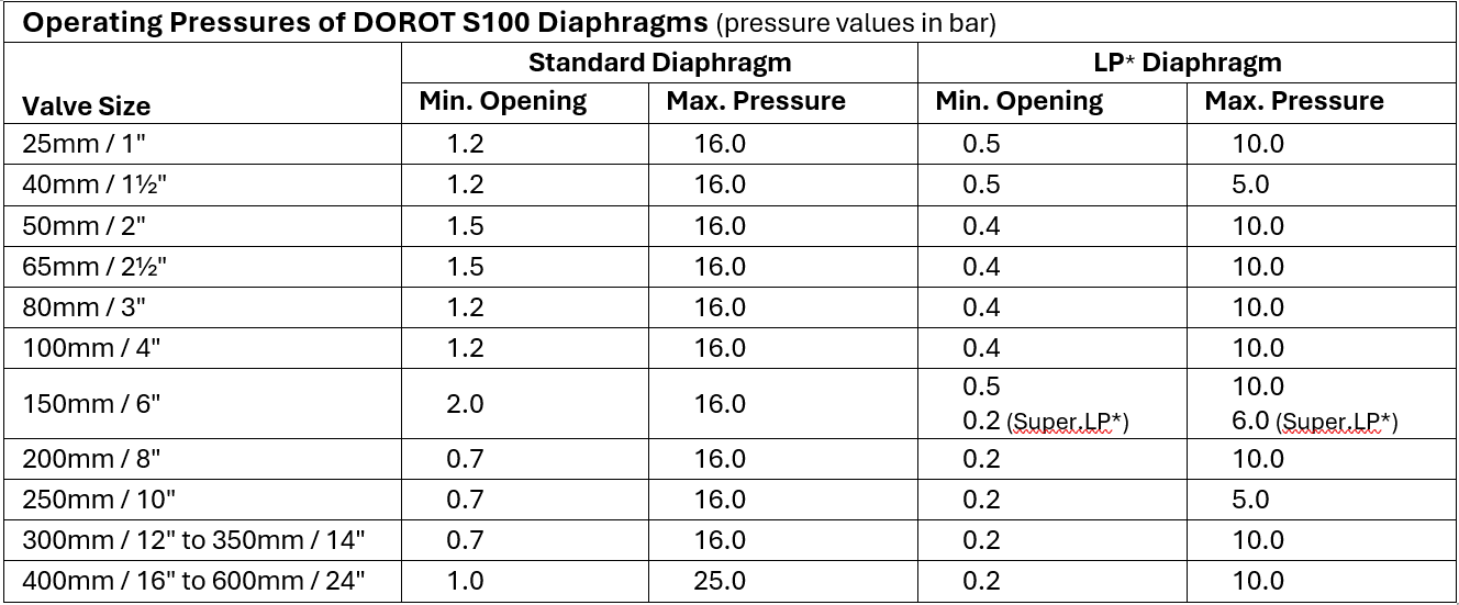
For DOROT S100 valves, replacing the standard diaphragm with a low-pressure (LP) diaphragm can significantly reduce the minimum pressure required for proper operation.
Benefits:
⚠ Notes:

* Note: LP = Low Pressure; Super.LP = Super Low-Pressure diaphragm option.
When line pressure is insufficient for valve operation, external pressurized media, such as compressed air or water, can be used to force open the valve. To use this option, the valve and/or the control-trim design needs to be modified to one of the following options:
The spring is removed from the control chamber of a standard control valve, eliminating the downward spring force which resists the opening, thereby enabling full opening of the valve at lower pressures. External control pressure, somewhat higher than the inline pressure, must be applied to ensure valve closure in the absence of the closure-assisting spring.
Benefits:
⚠ Notes:
This single-chamber valve, is held in the open position by an external spring. The valve remains open unless actively commanded to close. Closure requires a high enough external pressure-source to overcome both the spring force and the internal opening force.
Benefits:
⚠ Notes:
The control valve is forced to open by a vacuum that is generated via a flow-driven device (ejector, Venturi or vacuum pump). External pressure is used to generate sub-atmospheric pressure above the diaphragm, pulling the trim open even at zero inline pressure, and redirecting the external pressure into the chamber closes the valve.
Benefits:
⚠ Notes:
Here, a double-chamber version of the DOROT S300 valve is implemented, by inserting a separation disc between the diaphragm and the sealing plug. This forms a second control chamber below the diaphragm, into which external control pressure can be applied to force the internal trim upwards while the top control chamber is de-pressurized. Venting the lower control chamber and pressurizing the top one forces the valve into a drip-tight closed position.
Benefits:
⚠ Notes:
Where low-pressure conditions are intermittent, a bladder tank with a non-return valve can store higher pressure from the system during normal-pressure operation. This stored pressure can later be used to operate the valve when low-pressure conditions exist.

(*) Note: External media system costs are not included in the above relative cost ratings, and may vary significantly depending on whether suitable pressure sources already exist on site.
Selection of the most appropriate low-pressure solution should follow these prioritized criteria:
How to Choose the Right Solution
First, determine the minimum expected line pressure at the valve location. Then take the relevant course of action from the list below:
Important Note: Compare actual and designed pressure conditions to the specific valve in use. It is malpractice to require special and non-standard low-pressure valve configuration when simpler solutions may suffice. Always consult Aquestia technical support when conditions appear to require complex solutions, as DOROT valves often offer wider operating ranges than competitor products.
Hydraulic control valves can be successfully deployed in low-pressure environments, with appropriate adaptation. The range of solutions presented in this guide allows for customized approaches based on site conditions, available resources, and operational requirements.
Aquestia valves offer superior low-pressure capabilities compared to the market benchmark, with the DOROT S300 and DOROT S500 series operable at pressures as low as 0.2 bar with simple modifications, and effectively zero pressure through use of appropriate control systems.