Cavitation in hydraulic control valves happens when local pressure drops below the liquid’s vapor pressure, causing vapor bubbles to form and collapse inside or downstream of the valve. In water systems, cavitation can lead to noise, vibration, erosion, reduced performance, and premature valve damage. The best way to reduce cavitation risk is to review pressure-drop conditions, evaluate valve selection, and use anti-cavitation design or system-level mitigation where needed.
Modify system design:
Choose anti-cavitation valves or trim options, such as:
Select durable materials:
Contact Aquestia’s Applications Engineers, who are ready to assist you.
Cavitation is a common, yet potentially damaging, phenomenon in hydraulic control valves. It occurs when localized pressure drops below the vapor pressure of the liquid, forming vapor bubbles. These bubbles collapse violently, often causing severe damage to valve components and reducing both performance and service life. For this reason, understanding the causes and consequences of cavitation is critical for engineers and system designers. In this article, we explore how cavitation develops, its effects on valves, how to assess the risk of occurrence, and the methods available to prevent it.

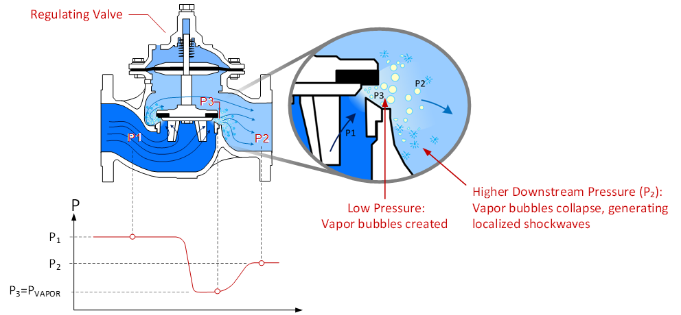
In a throttled regulating valve, fluid velocity in the vena-contracta (the narrowest flow passage between the seal and the seat) can be extremely high. This extreme velocity causes a localized pressure drop, potentially reaching as low as vapor pressure – a sub atmospheric pressure value at which water boils and vapor bubbles form. These vapor cavities travel downstream, where velocity decreases and pressure rise. As a result, the vapor bubbles collapse and implode, generating localized shock waves that can cause various effects, including:
Noise
When the vapor bubbles collapse, noise is emitted across a broad frequency spectrum. Several factors influence noise levels, including the bubble collapse rate, fluid properties, and valve geometry. It travels through building walls and connected pipelines, disturbing residents and workers. However, it is more than just a nuisance – it signals the release of destructive energy within the valve.
Vibrations
Produced by the uneven forces generated during the collapse of vapor bubbles, vibrations can propagate through the valve, piping, and supporting structures, potentially leading to mechanical fatigue, loosening of connections, and long-term structural damage. The severity of vibrations depends on the intensity of the cavitation, the system’s structural rigidity, and resonance effects within the piping network.

Impact on Hydraulic Performance
In addition to the typical effects discussed above, cavitation can significantly alter fluid dynamics:
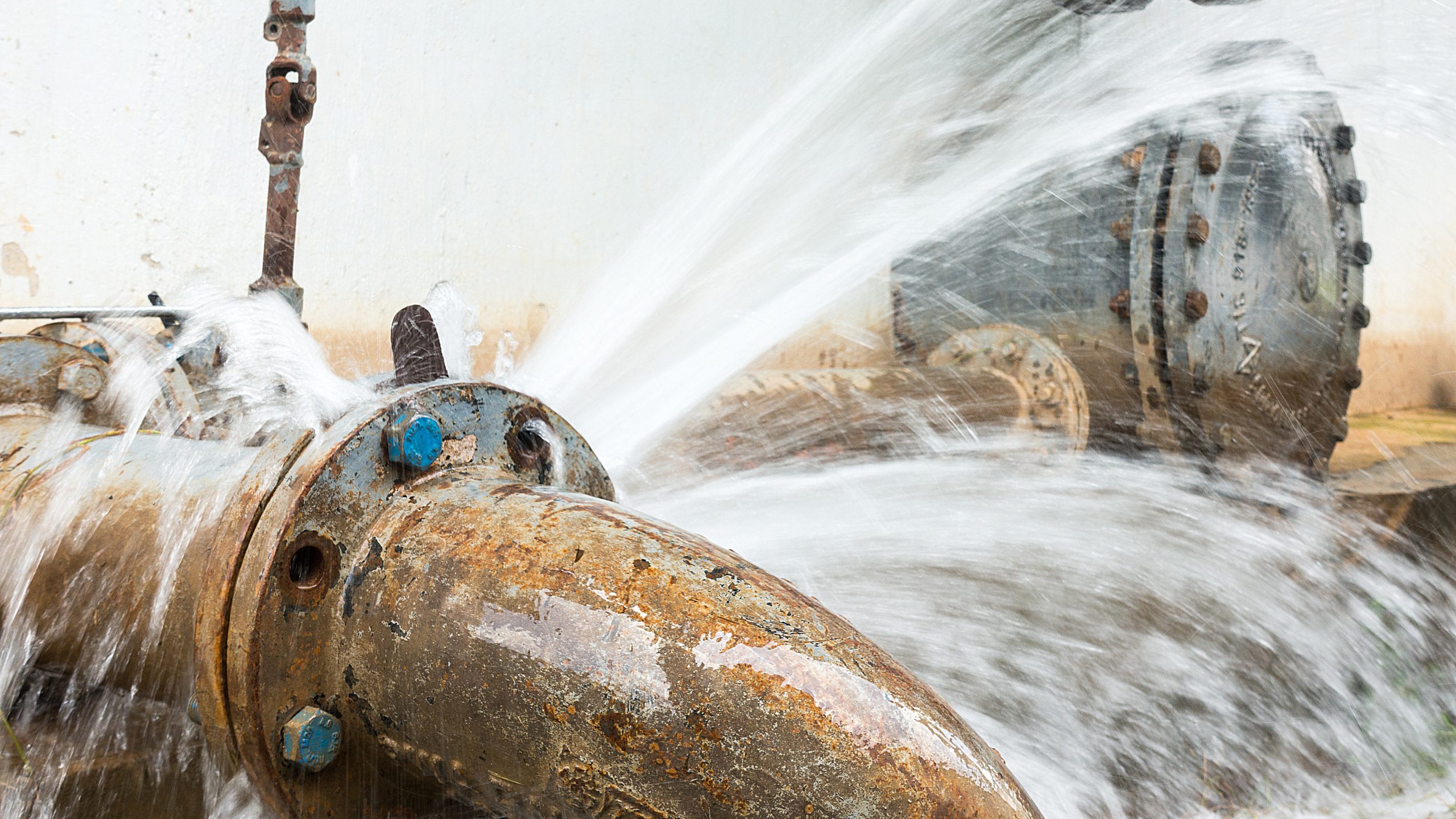
Cavitation Erosion
Cavitation causes potholes to form on the downstream side of the throttled valve’s body and internal trim. The erosion happens in phases. In the incubation phase, material deformation begins, but no measurable weight loss occurs. This is followed by the acceleration phase, in which repeated stress cycles lead to rapid material loss. Prolonged severe cavitation can lead to material loss that is significant enough to cause cavities that penetrate the valve body or damage internal components, potentially impairing valve functionality. Material properties like hardness, ductility, and surface finish significantly impact erosion rates.
Cavitation is categorized into three main levels: Incipient Cavitation, Critical Cavitation, and Choking Cavitation.
The severity of cavitation is influenced by factors such as:
The basic calculation for predicting cavitation damage is:

where:
σ : the cavitation coefficient (a factor of the specific operating conditions).

P1 : upstream pressure
P2 : downstream pressure
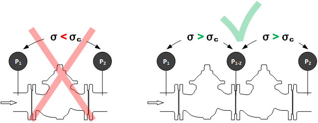
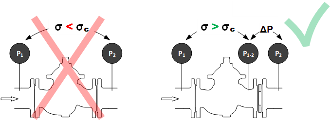
Cavitation damage occurs when: σ < σc
where:
σc : the critical cavitation coefficient of the specific valve model

Cavitation resistance, represented by the σc cavitation coefficient, can be tested using computerized flow simulations. However, validating these results requires specialized equipment and specific conditions. Such conditions are available in select academic laboratories, like those at Delft University of Technology and the University of Utah, where DOROT hydraulic control valves have been tested.
An alternative method to assess cavitation risk is through a graphical representation of the above calculations, commonly provided by the valve manufacturer. Below is the cavitation chart for DOROT S300 hydraulic control valves:

NOTE:
Cavitation damage accumulates over time, typically requiring several months of severe conditions to affect system integrity. If cavitation occurs only intermittently—lasting seconds, minutes, or even hours annually—while the valve otherwise operates safely, no special action need be taken. Example: a Safety, Quick-Acting Pressure Relief Valve (DOROT function code ‘QR’) remains closed most of the time and, when open, experiences extreme cavitation for only a few minutes before closing again. Such brief exposure is insufficient for significant damage to accumulate over the valve’s lifespan.
Materials with high resilience to cavitation typically possess:
Flow-path design can also contribute to cavitation resistance, by directing the vapor bubbles away from the valve body and internals, and toward the center of the flow stream, where it causes no damage.
Strategies to prevent cavitation include:
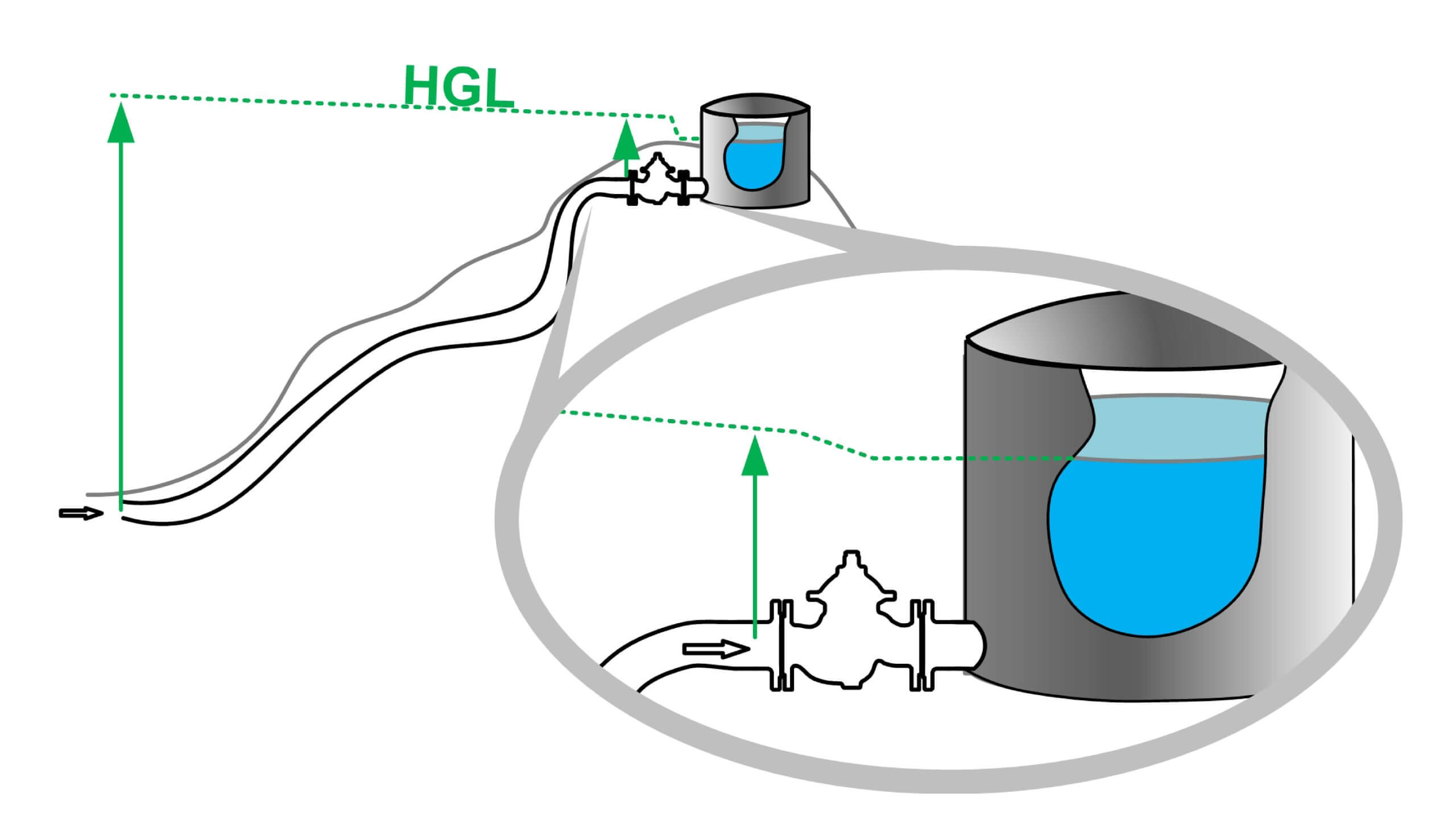
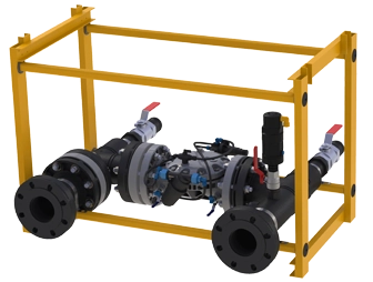
Installing two or more valves in series, with each valve controlling part of the required ΔP across the system. For example, two or more Aquestia’s Pressure Sustaining/Relief valves (function code ‘PS[R]’) can be installed to ensure that they don’t operate under cavitation conditions.
Trim Design: Use anti-cavitation cages and optimized flow-path trims to control pressure drops. A good example of this is the DOROT Anti-cavitation trim design (model code ’30F’). The unique design of this trim causes the vapor bubbles to implode in the flow, far from the valve internals, dramatically reducing the risk of cavitation damage.

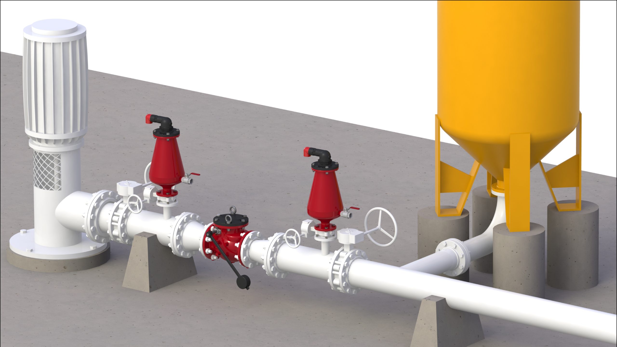
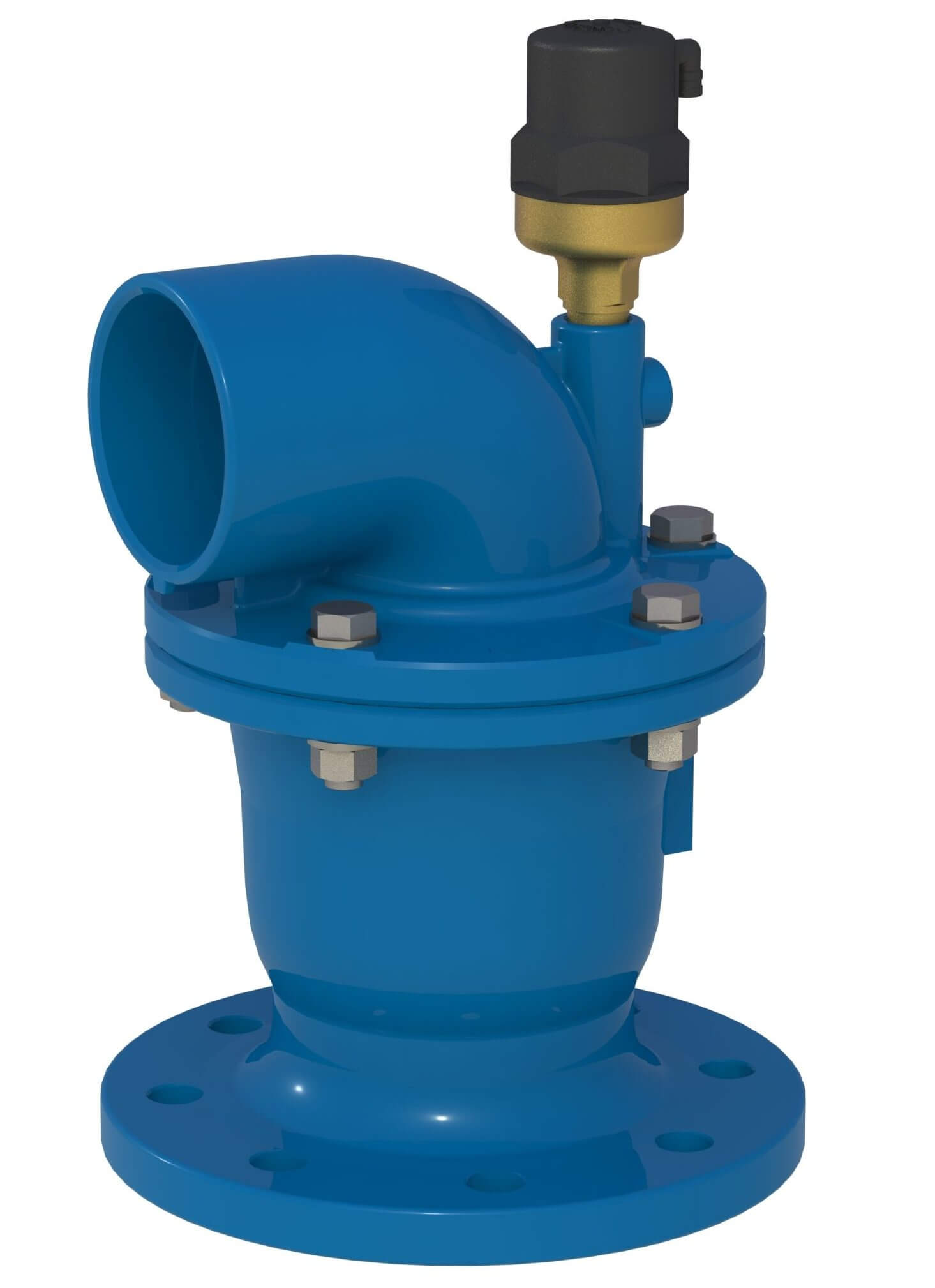
Anti-Cavitation Air-Suction: This is a unique solution provided as an optional feature in DOROT S100 hydraulic control valves. Special air-suction devices allow jets of atmospheric air to enter the low-pressure area in the vena-contracta, thus preventing the pressure from dropping below the vapor pressure, thereby preventing vapor bubbles from forming. The air bubbles do not implode, and serve as shock absorbers, further limiting the risk of cavitation damage.

While choosing valve construction materials – such as stainless steel – that resist both erosion and corrosion will not prevent cavitation altogether, it can extend the time before critical damage occurs. This approach is suitable in systems where cavitation conditions exist only during part of the valve’s operation time.
In cases where cavitation is unavoidable, selecting valves specifically designed to withstand cavitation effects can significantly prolong service life.
Bonus Advice: Reduce noise caused by tank filling
Strategies to mitigate noise and vibration issues include:
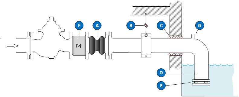
High-frequency vibrations traveling through the pipe can radiate as noise from the pipe walls. Use a flexible or soft connection between the valve body and the downstream pipe (see ‘A’ in the sketch below) to help absorb vibrations and noise, preventing their transmission into the piping system.
Apply flexible or soft isolation at points where pipes connect to the building structure (see ‘B’) or pass through walls (see ‘C’) to minimize noise transfer.
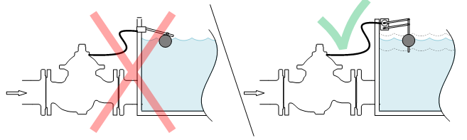
Although not related to cavitation, tank filling is a common source of substantial noise in residential buildings. To minimize this:
Avoid allowing the filling pipe to discharge above the water surface. Instead, extend the pipe into the tank (see ‘D’).
If an orifice plate is installed, place it at the open end of the pipe, inside the tank (see ‘E’).
Control valves operating with high upstream pressure and relatively low downstream pressure may be subjected to damaging cavitation, a phenomenon that can negatively impact control valves and overall system performance. By understanding its causes, effects, and mitigation strategies, engineers can design and operate systems more effectively, reducing the associated risks.
For an assessment and help selecting the appropriate mitigation method for your specific case, please contact Aquestia’s Technical Support.
Cavitation is caused by the local pressure inside the valve dropping below the liquid’s vapor pressure. This typically happens at the vena contracta, where flow velocity is highest and static pressure lowest. The most common triggers are a high pressure drop across the valve, low downstream pressure, incorrect sizing, and high flow velocity.
The clearest signs are a distinctive noise resembling “gravel flowing through the pipe,” noticeable vibration in the valve and adjacent piping, and unstable flow or pressure control. Over time, disassembly reveals characteristic sponge-like erosion on valve internals — pitting that is unmistakable once observed.
Cavitation causes mechanical erosion of valve internals through repeated micro-jet impacts from collapsing vapor bubbles. This leads to loss of sealing, loss of control accuracy, premature valve failure, and damage to downstream piping. In critical systems such as fire protection or municipal water supply, cavitation also introduces operational risk and unplanned maintenance costs.
Prevention strategies include multi-stage pressure reduction across two or more valves in series, anti-cavitation trim that disperses the pressure drop within a single valve, correct sizing based on actual flow and pressure data, and system-level changes such as adding downstream back-pressure or orifice plates. Material upgrades extend life when full prevention is impractical.
Yes — pressure reducing valves are among the most common applications where cavitation occurs, because their function is to drop pressure across a single restriction. When the ΔP is large relative to downstream pressure, the cavitation index drops into the damaging range. PRVs in high-rise buildings, deep municipal networks, and irrigation pressure-zone interfaces are particularly susceptible.
An anti-cavitation valve should be considered whenever the calculated cavitation index σ falls below the manufacturer’s recommended threshold for continuous service. Practically, this often applies to applications with pressure ratios above 3:1, low downstream pressure (close to atmospheric), continuous high-flow operation, and any installation where valve replacement is operationally difficult or expensive.
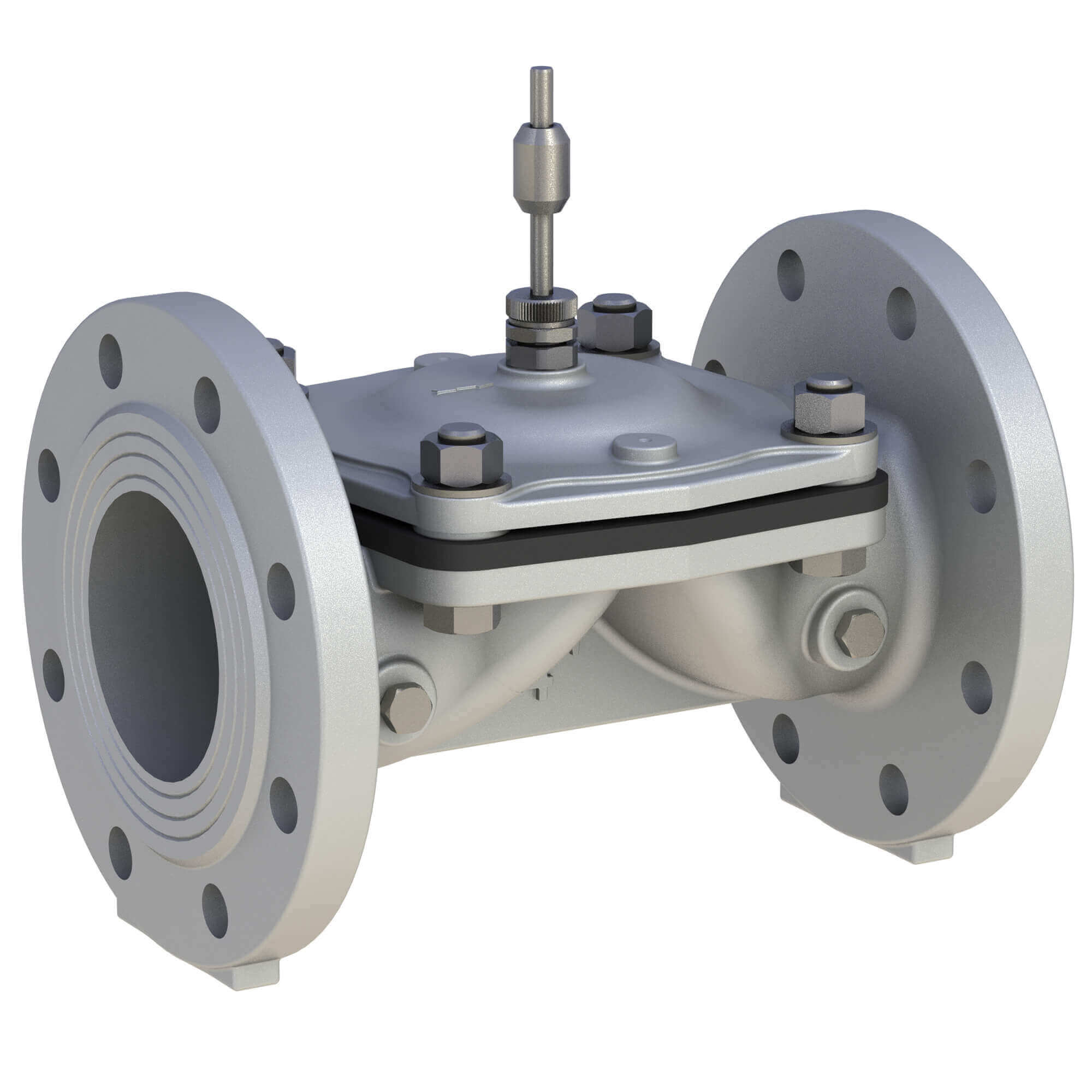
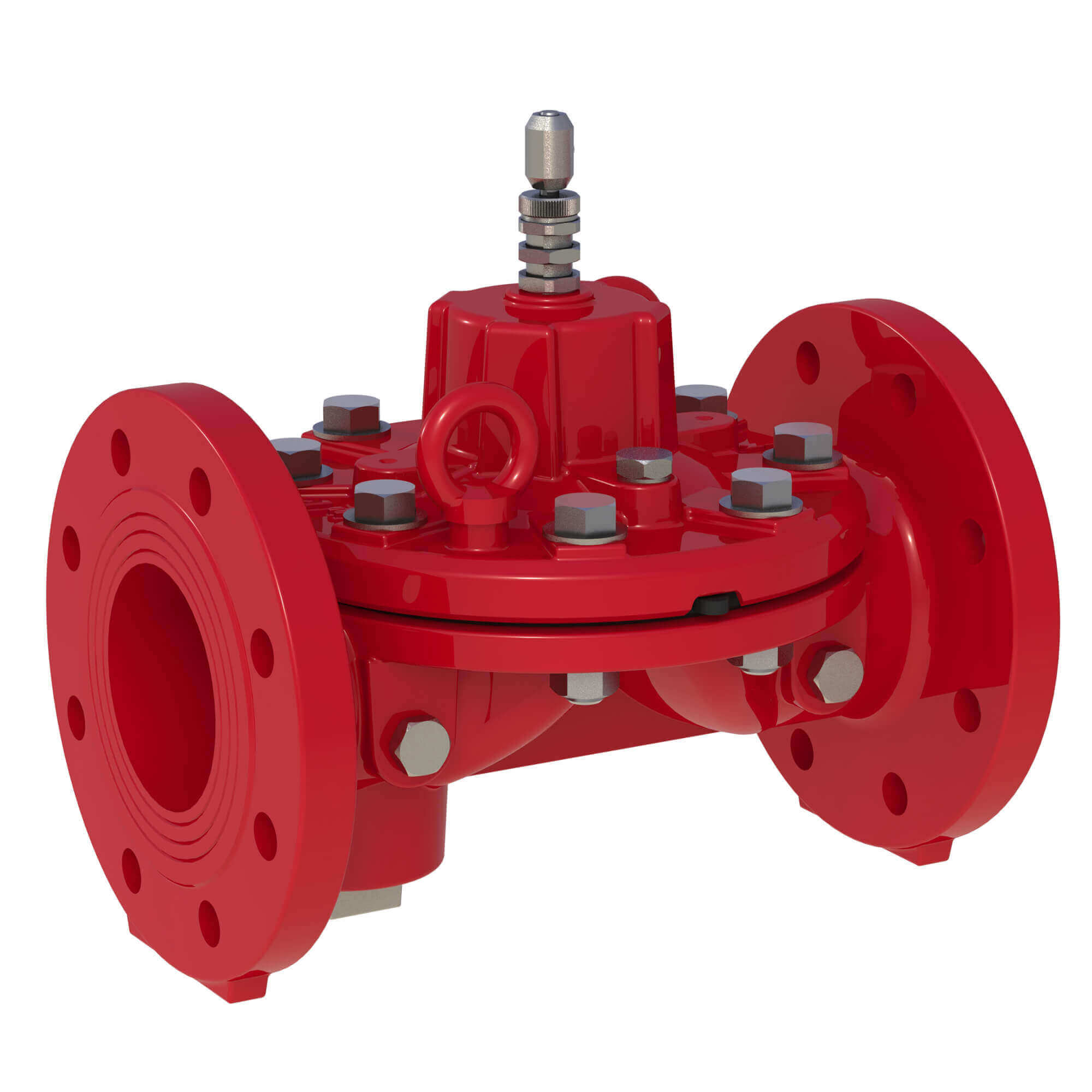
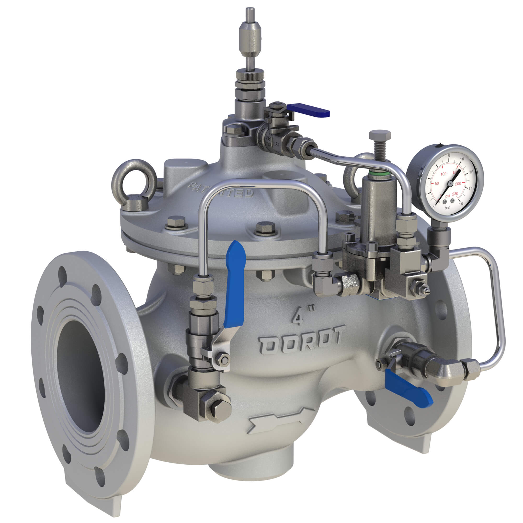
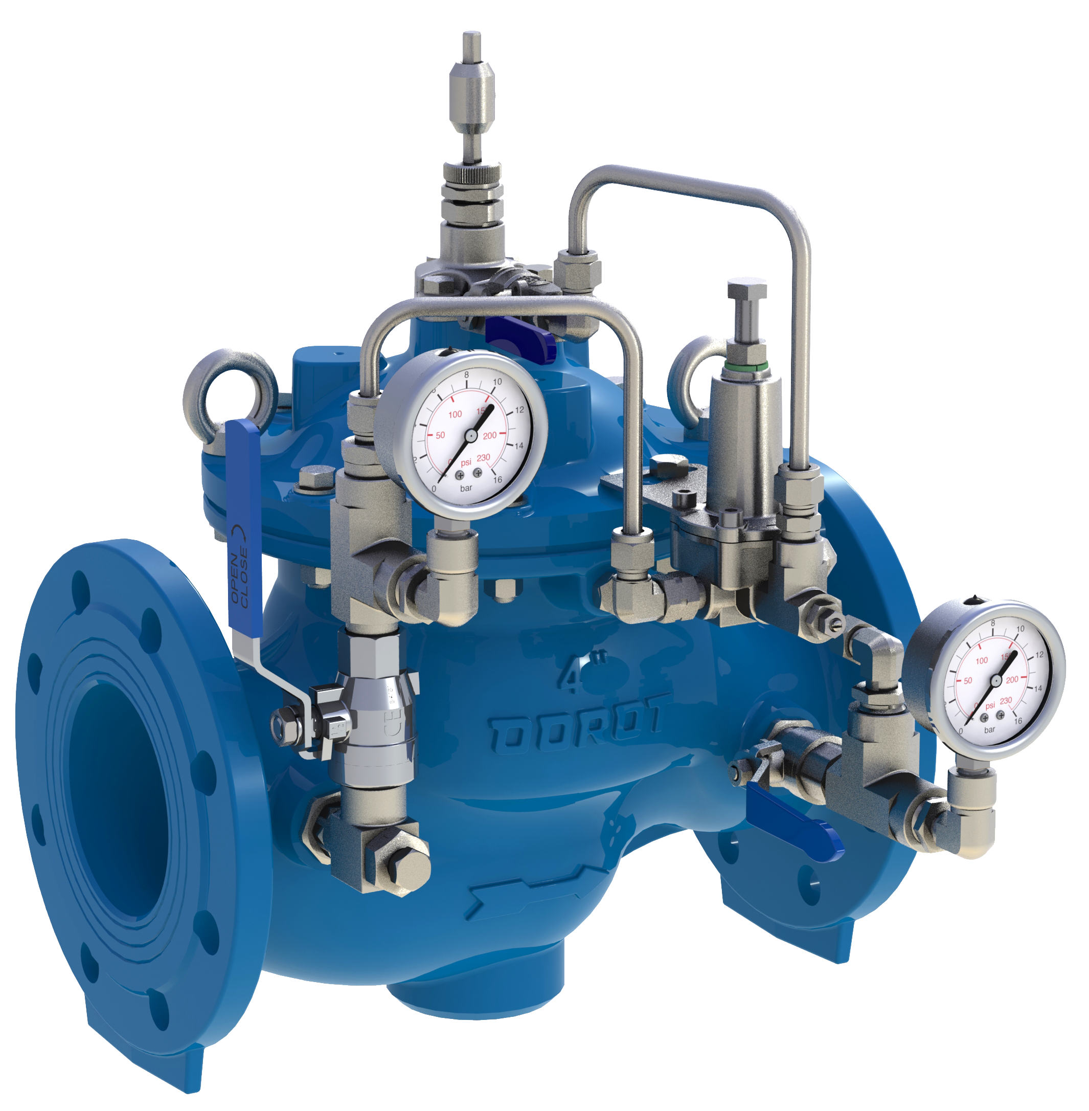
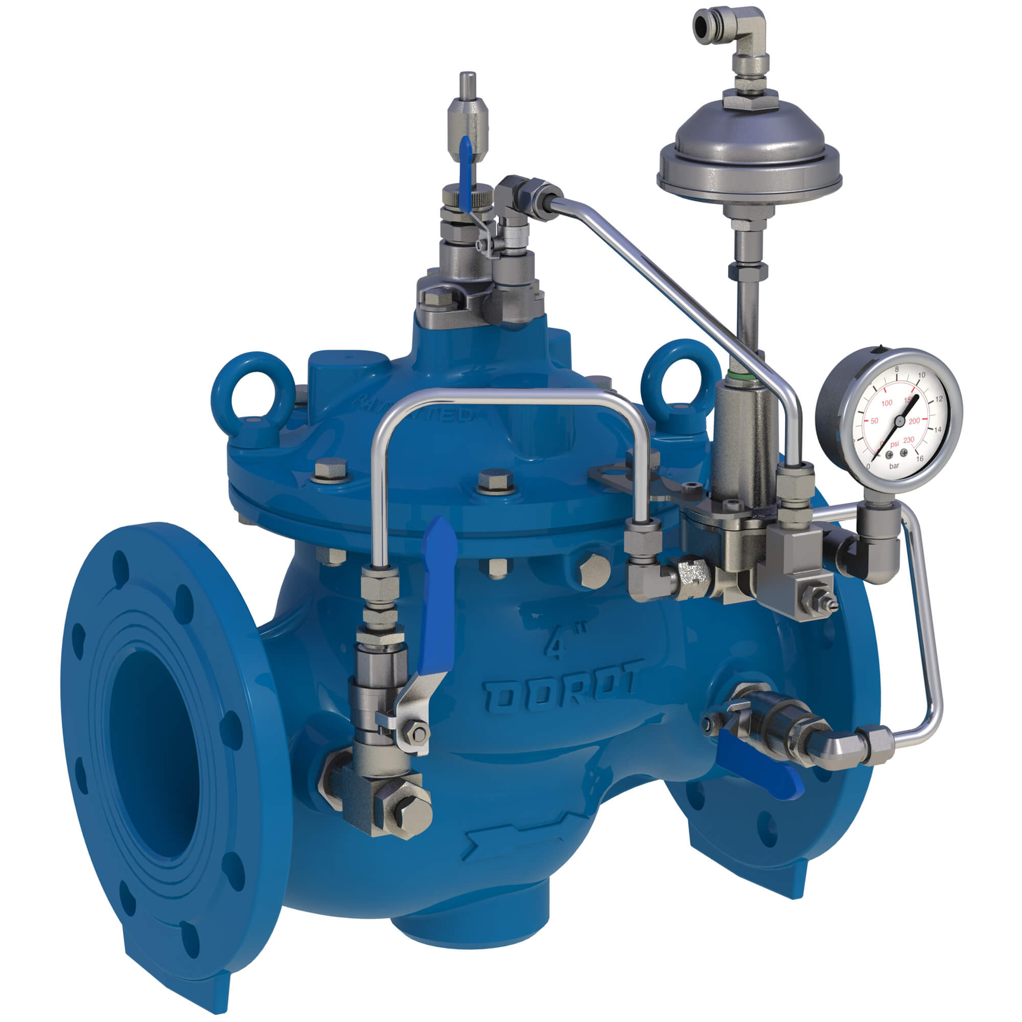
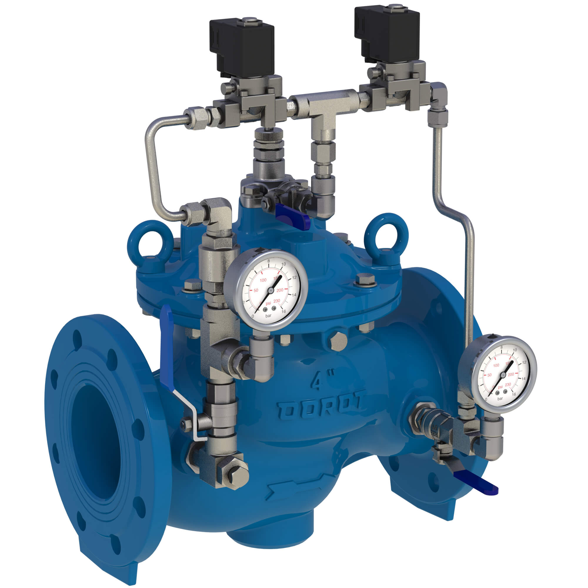
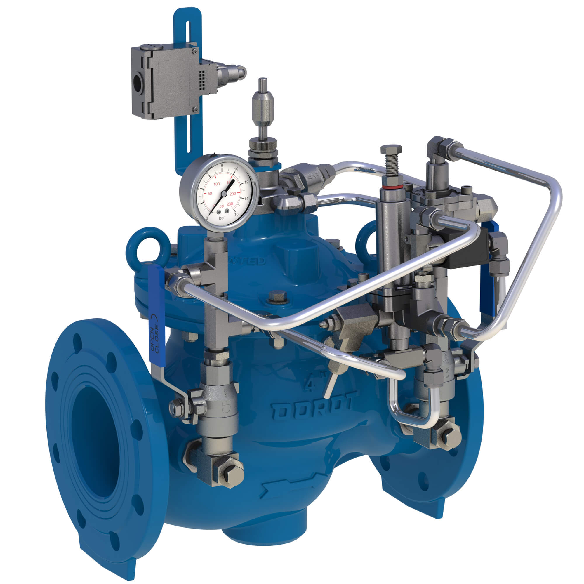
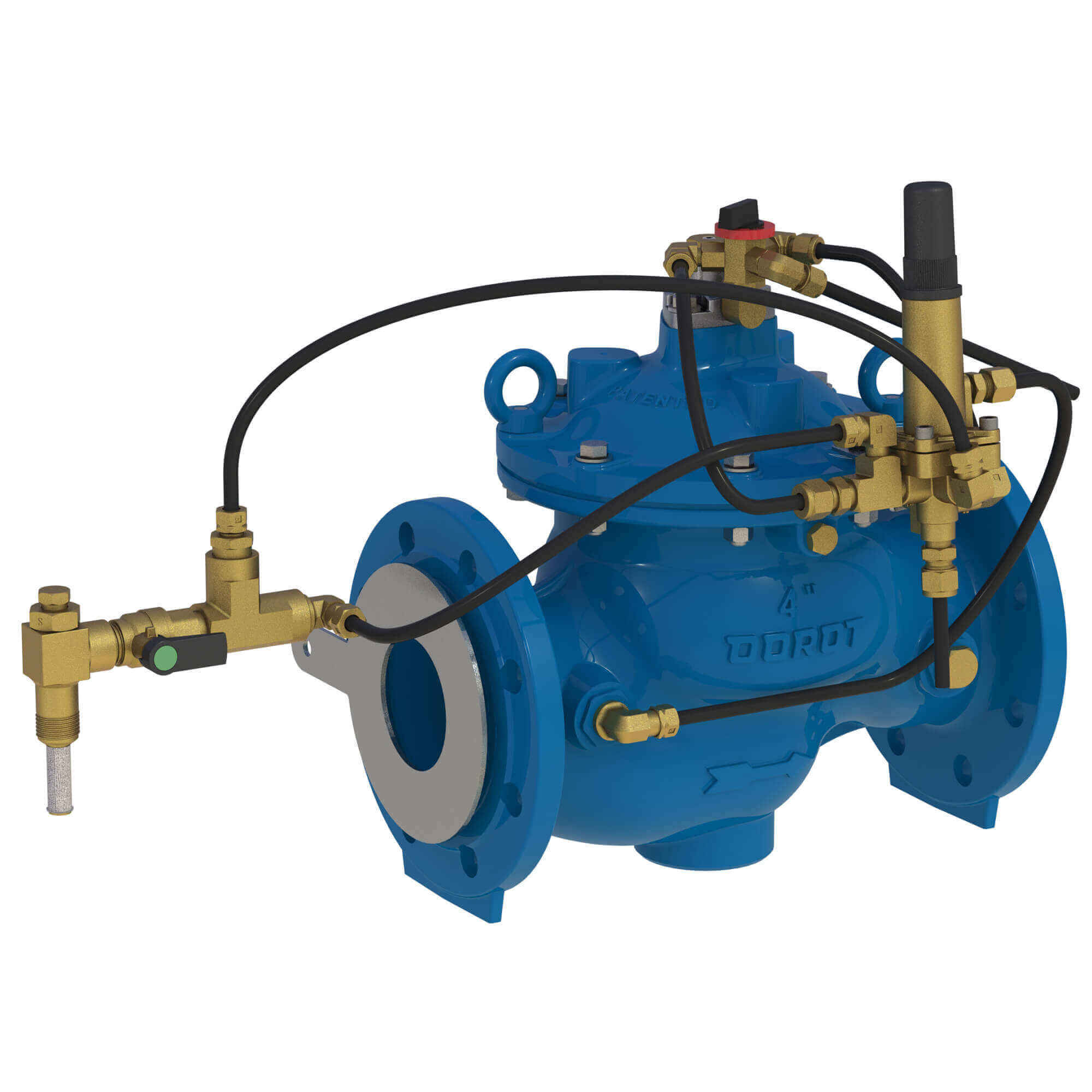
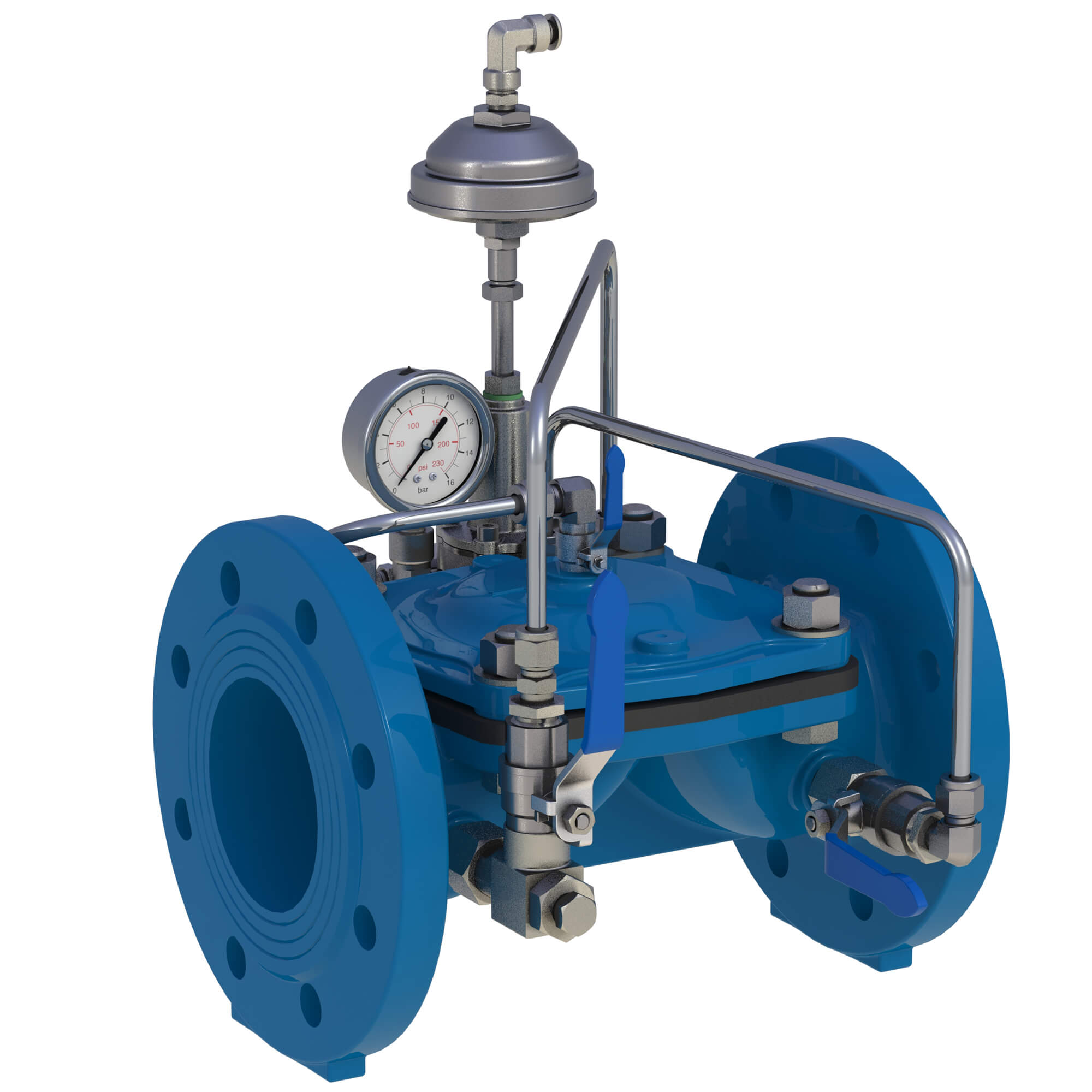
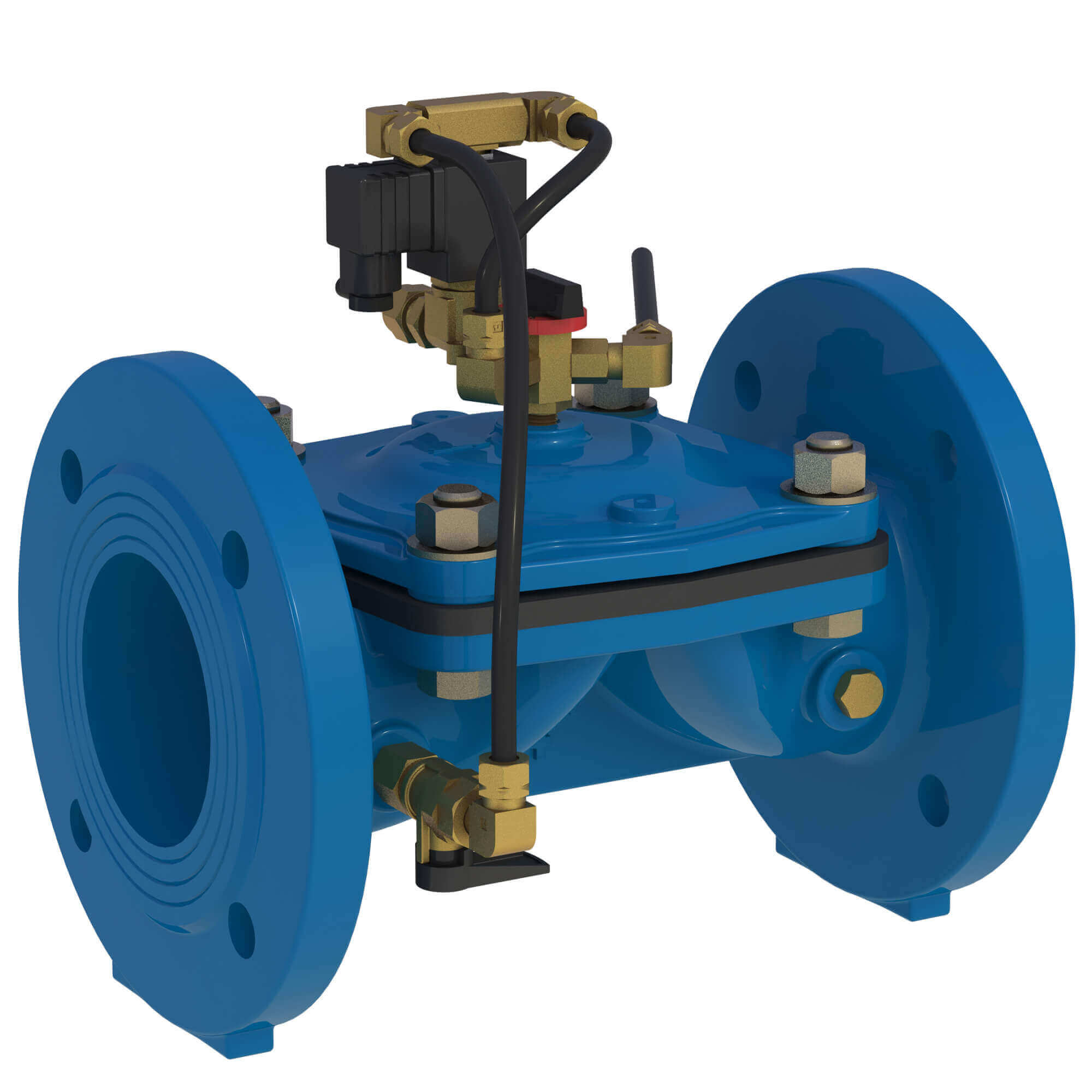
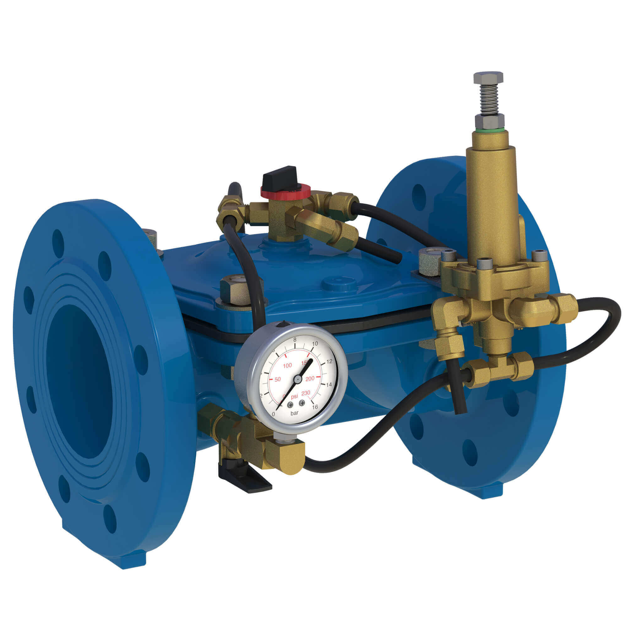
![Arisense Swg – DOROT S300 PR[D] WW](https://www.aquestia.com/wp-content/uploads/2024/12/WW-30-I-D-4-IS16RF-PRD2W-SS-EB_left.jpg)
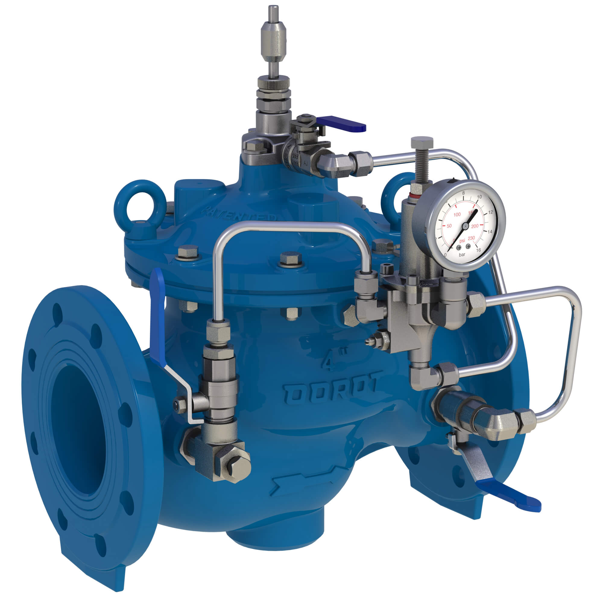
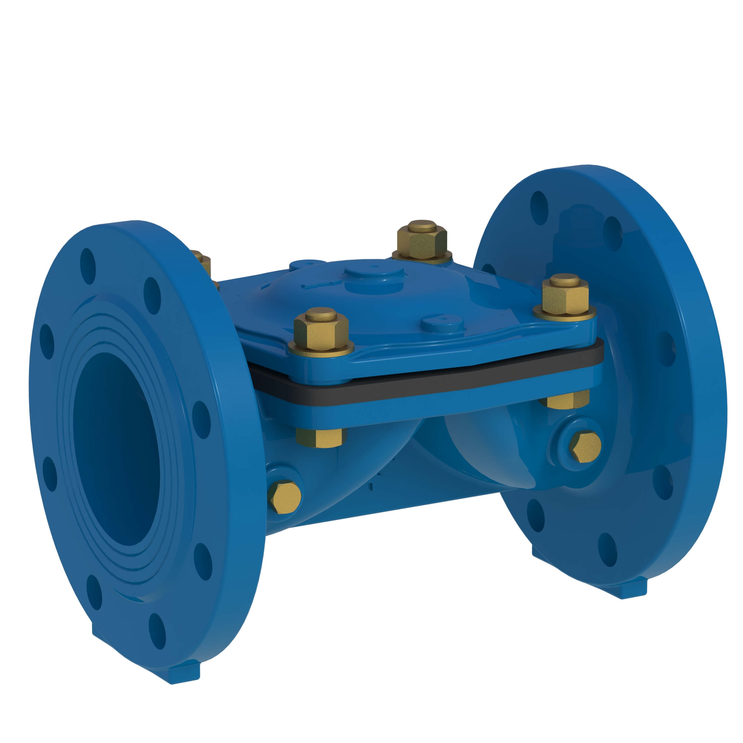
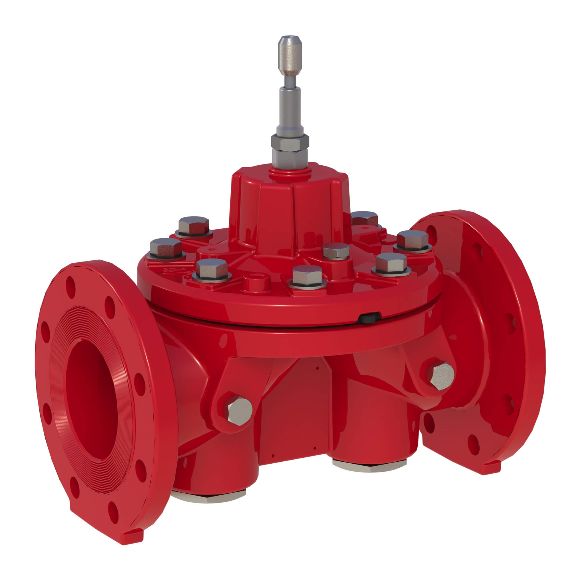
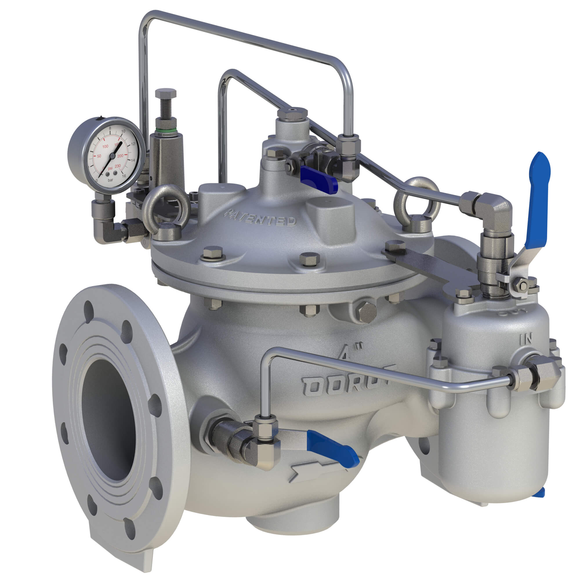
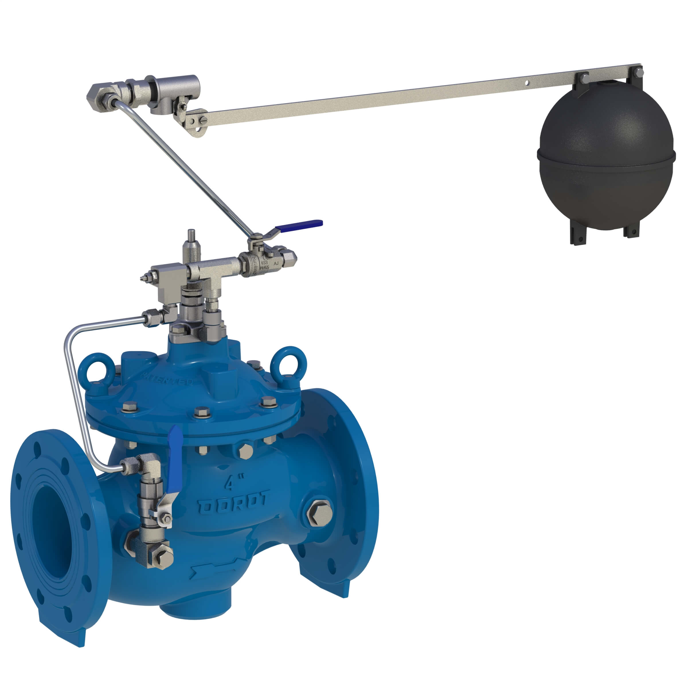
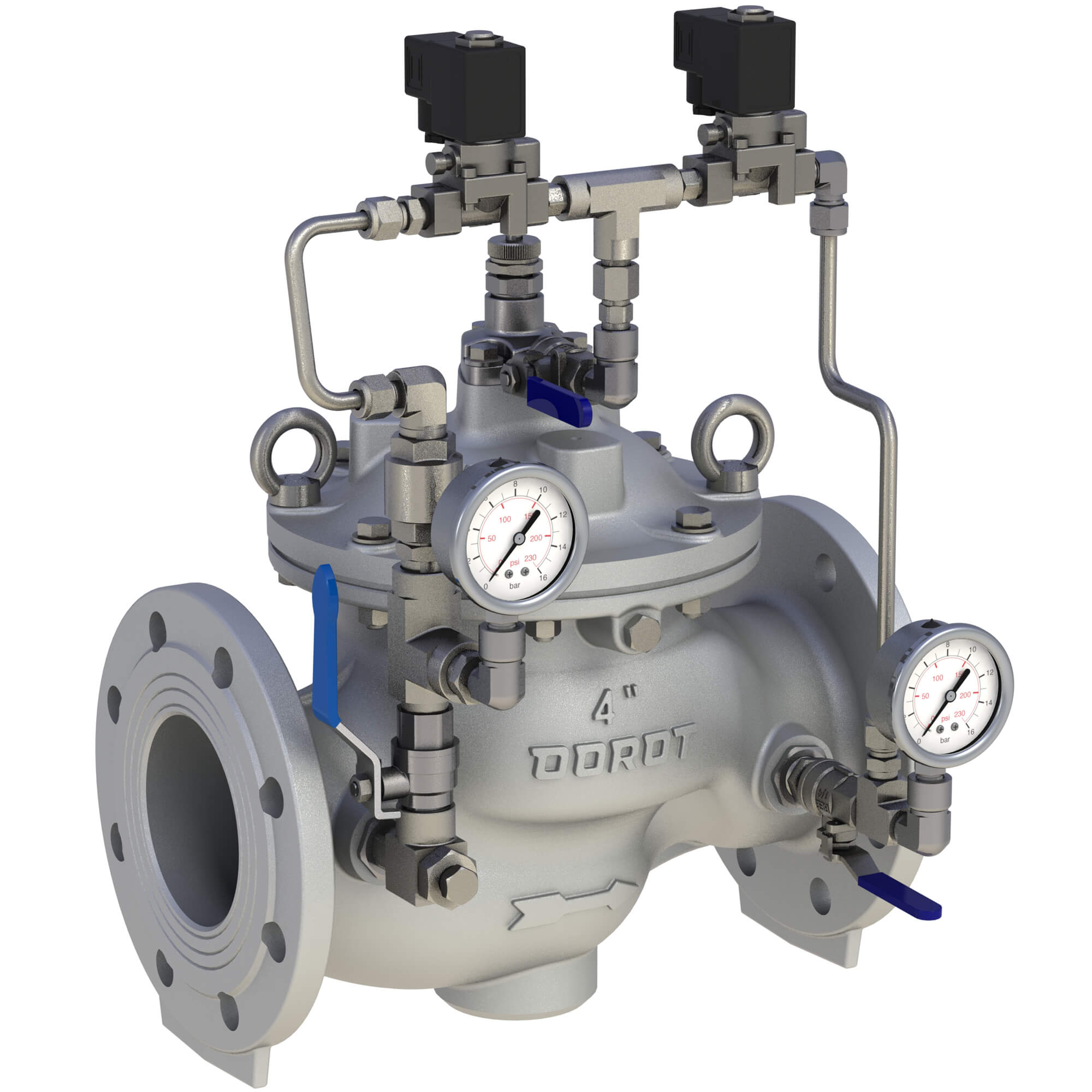
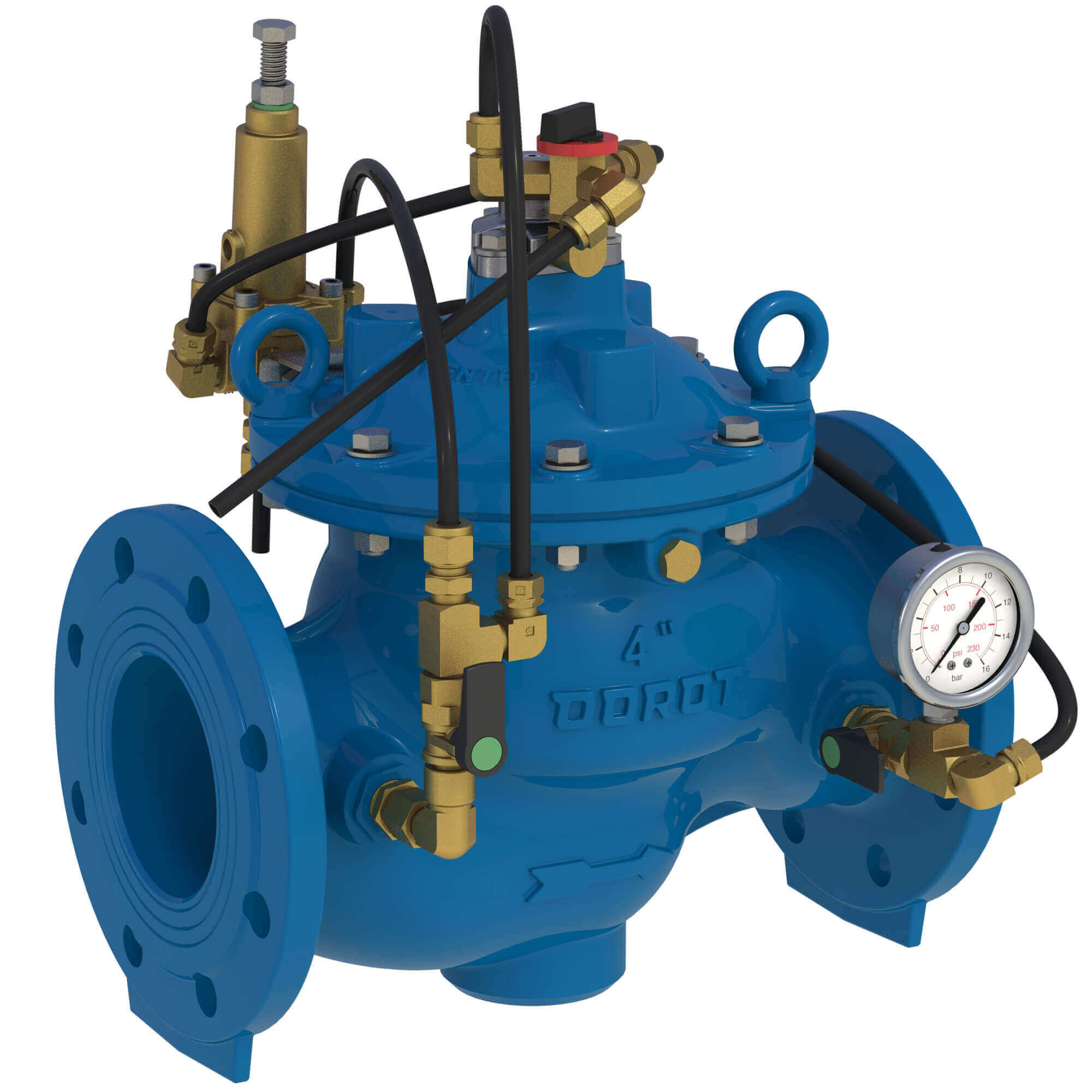
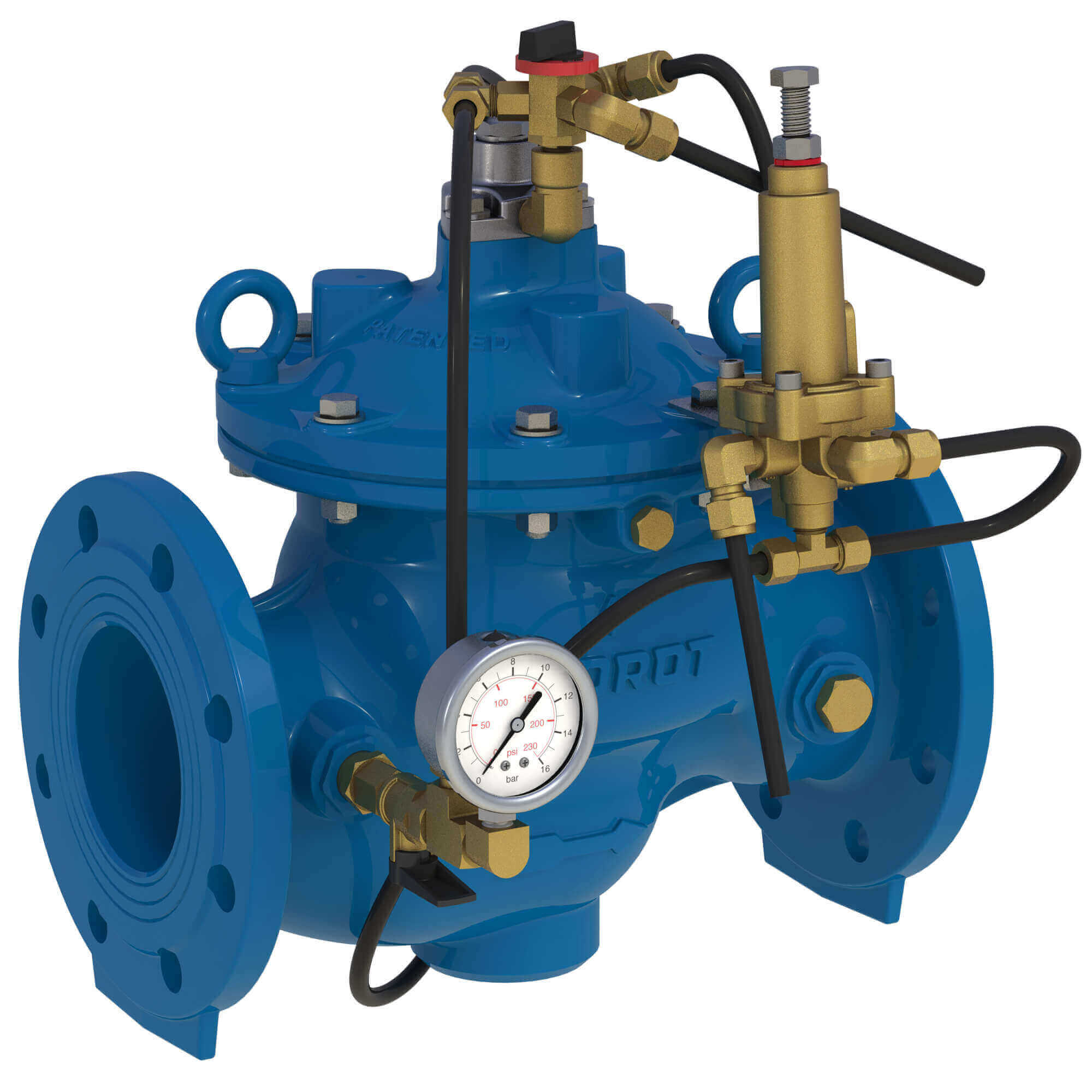
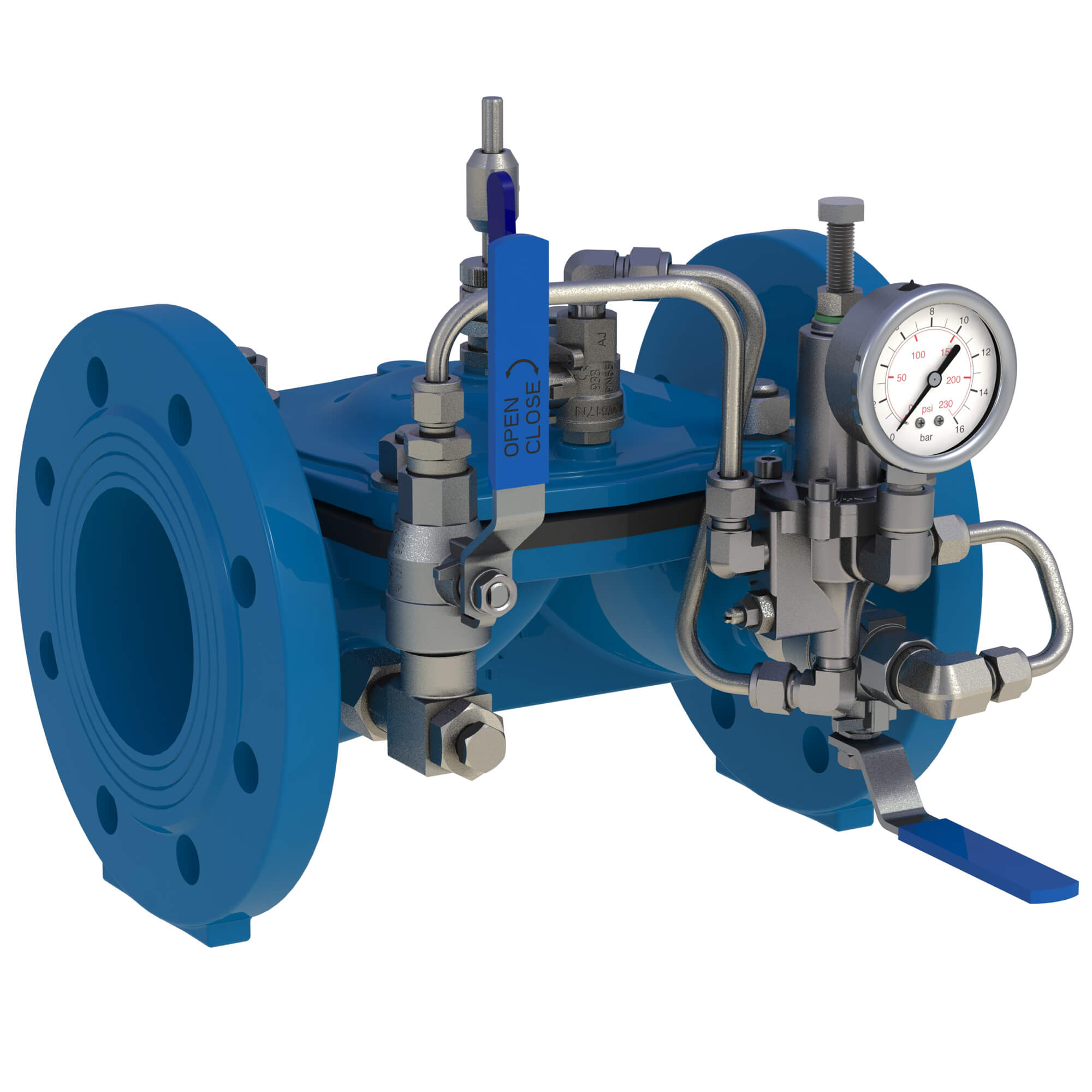
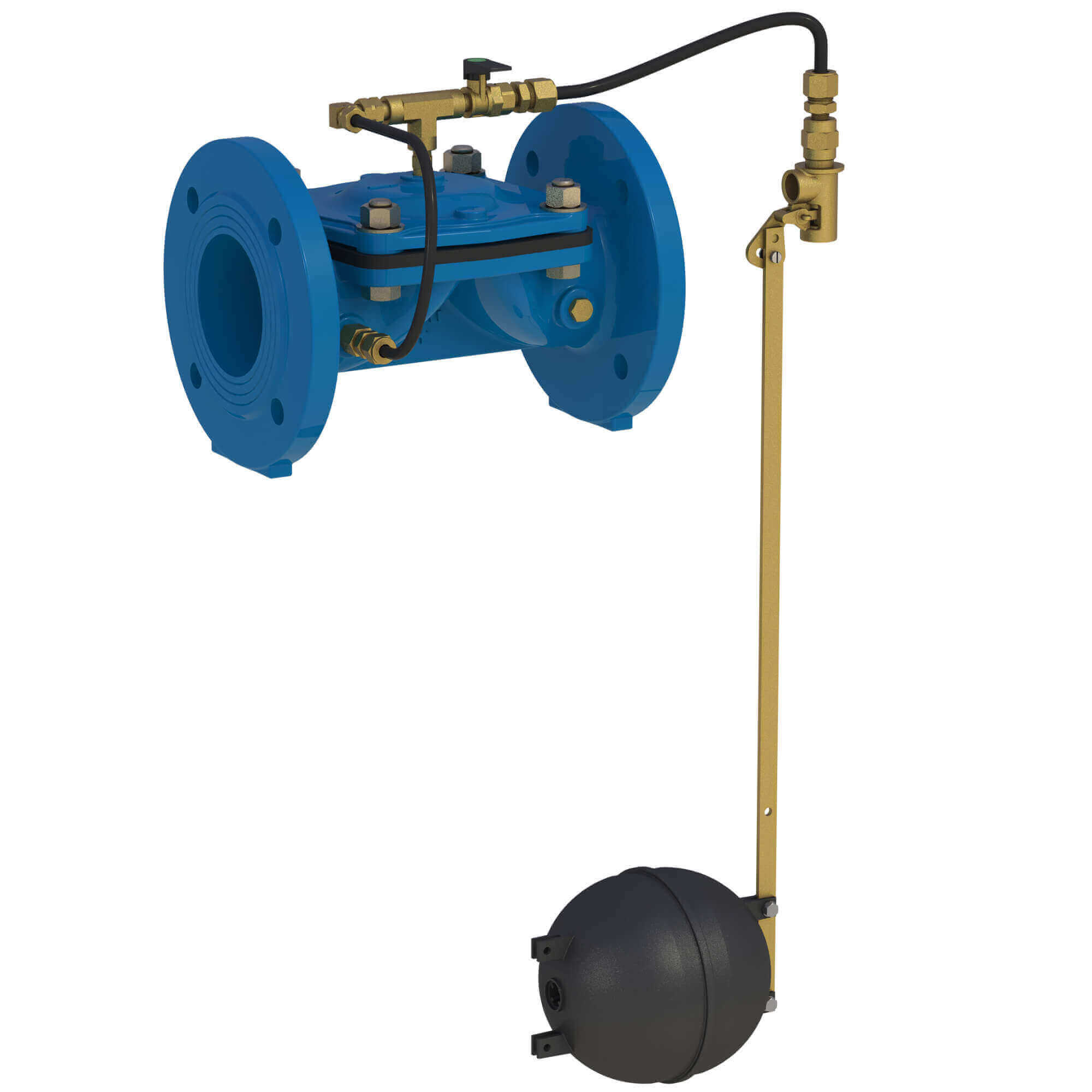
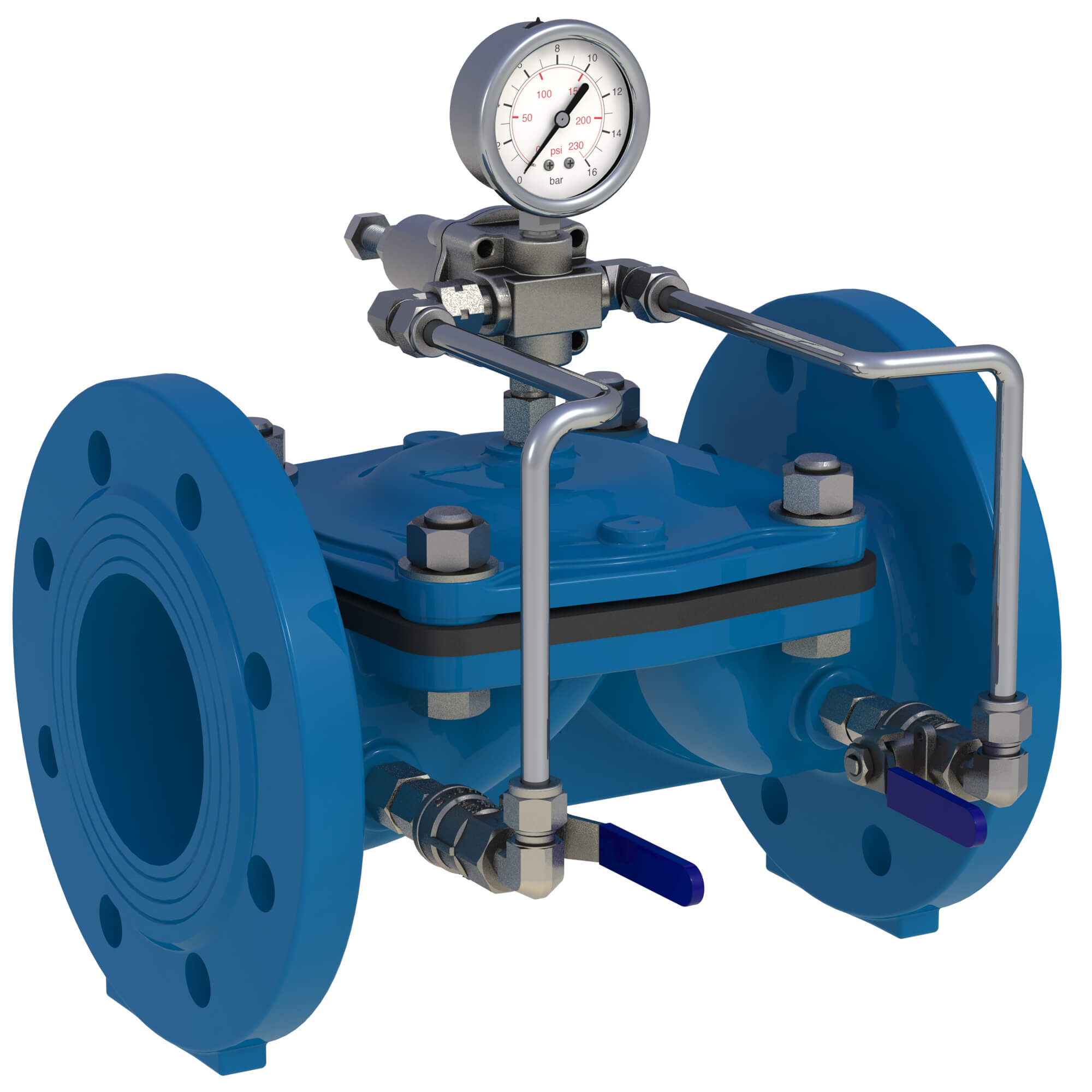
![Arisense Swg – DOROT S300 PS[R] MIN](https://www.aquestia.com/wp-content/uploads/2025/02/MI-30-I-4-IS16RF-PSR-2W-NS_left.jpg)
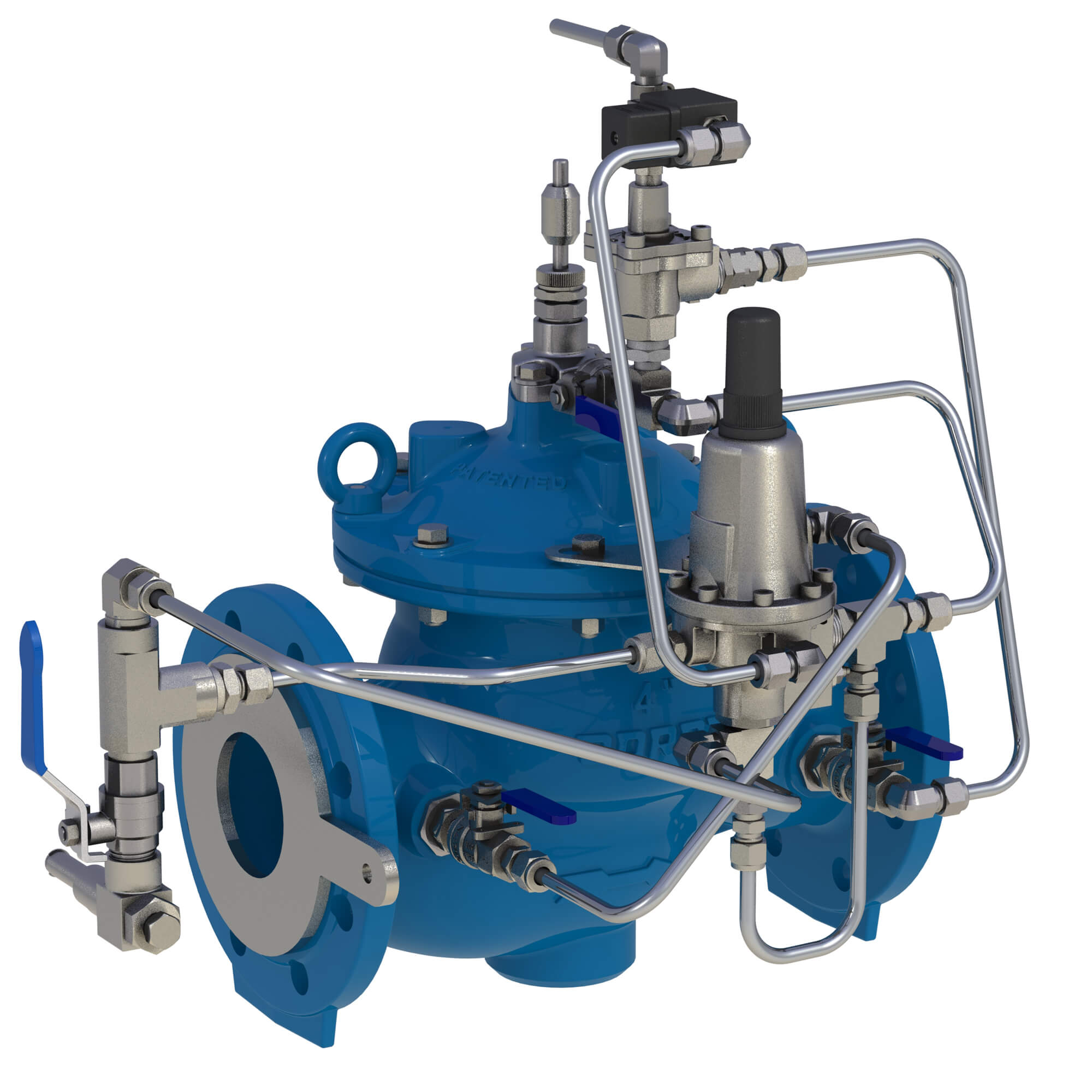
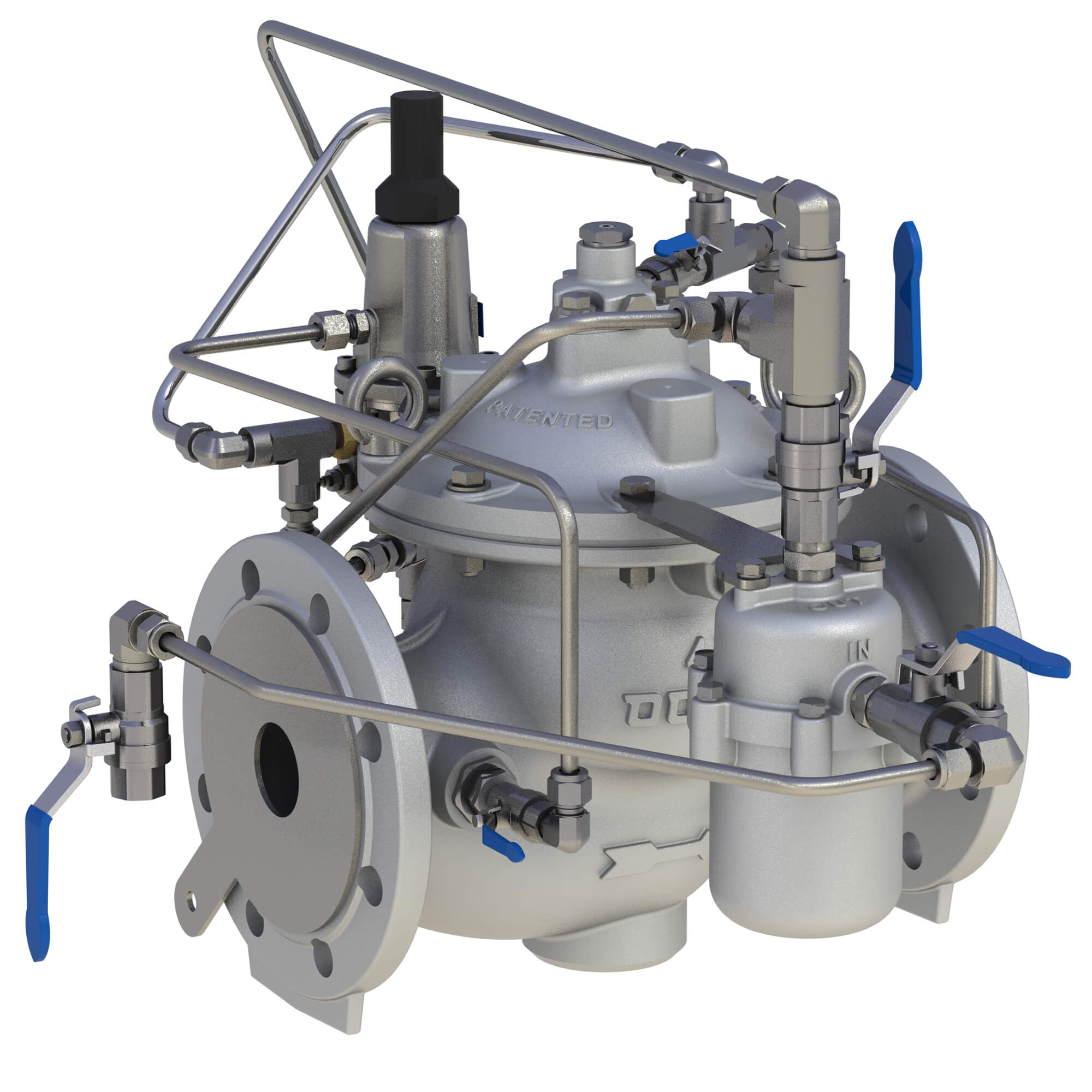
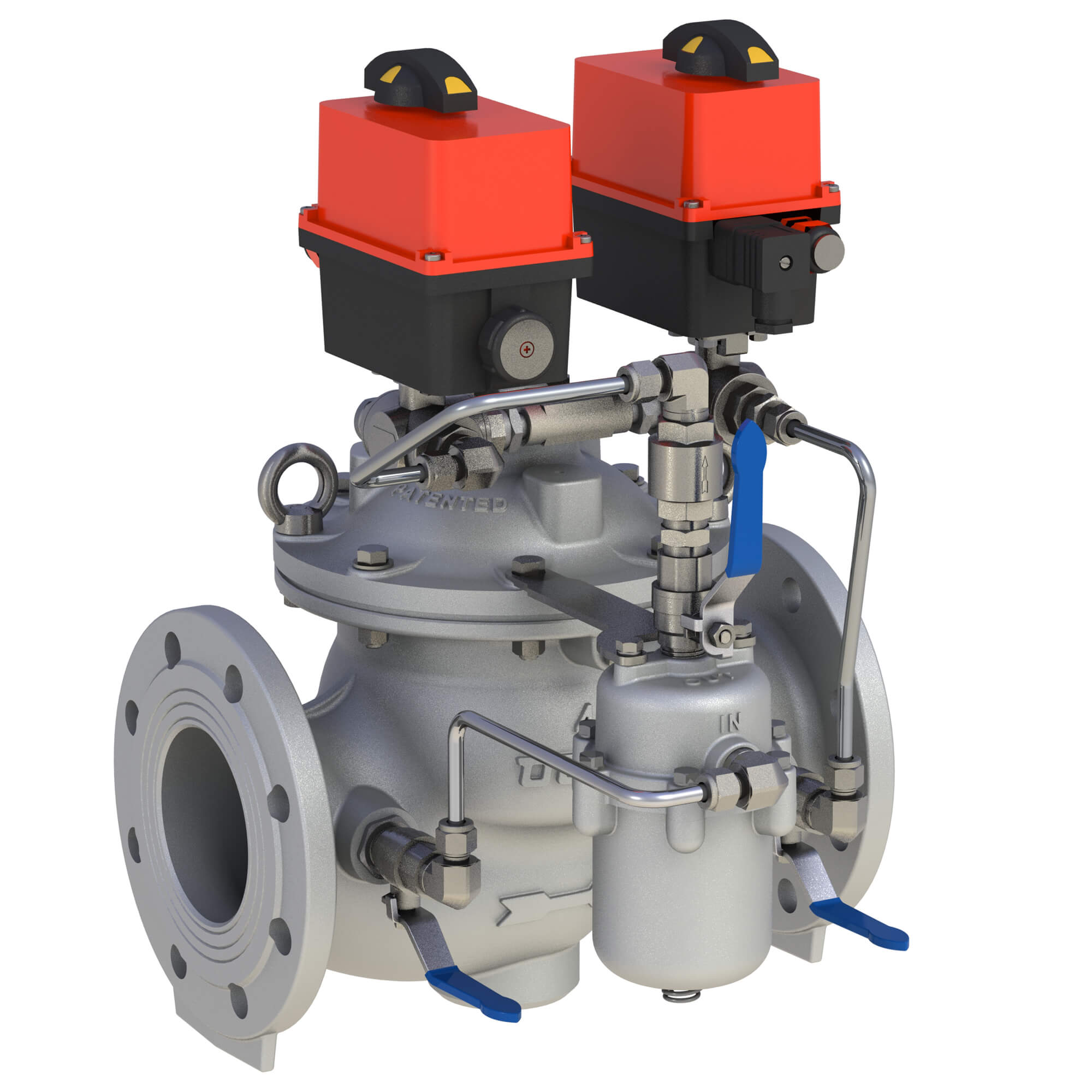
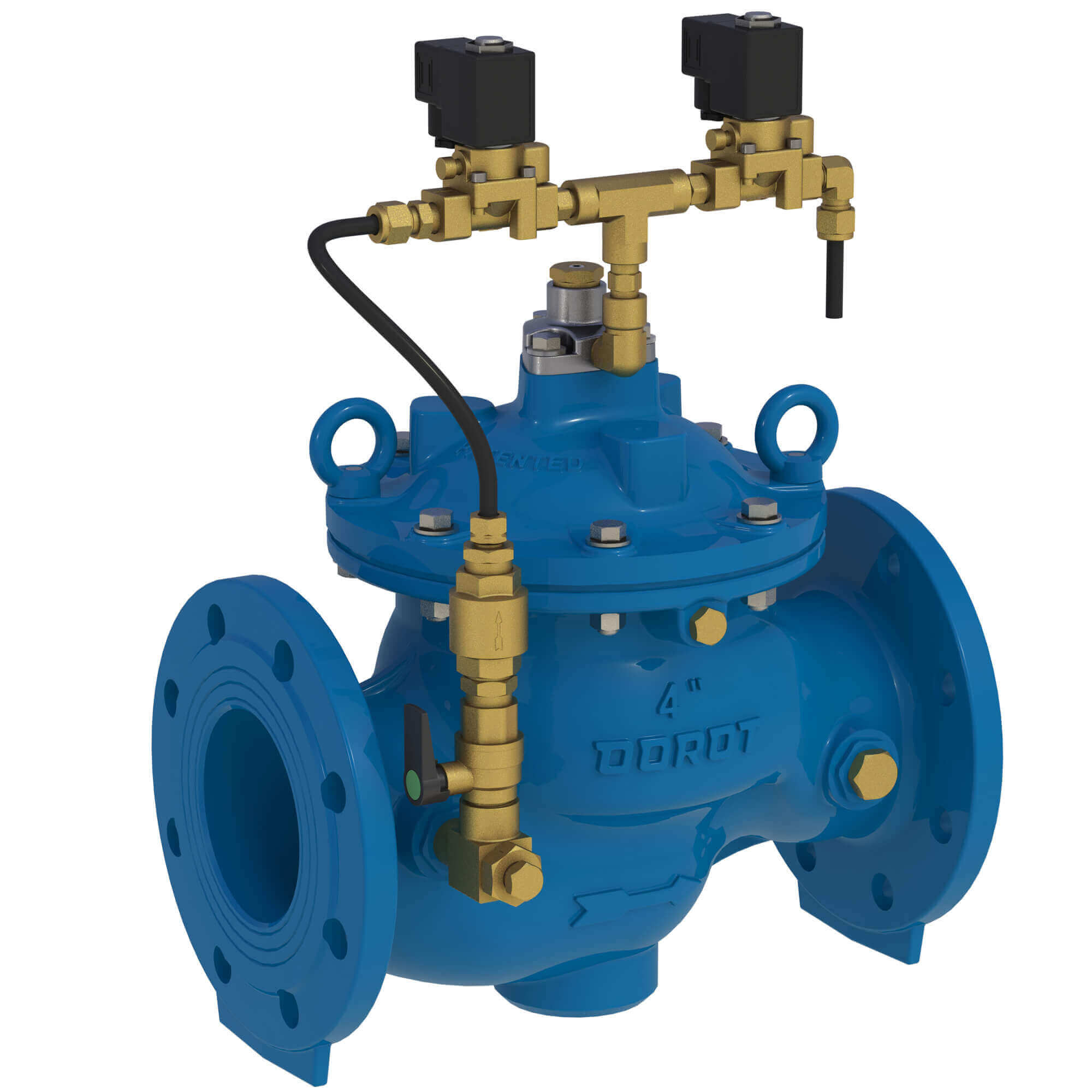
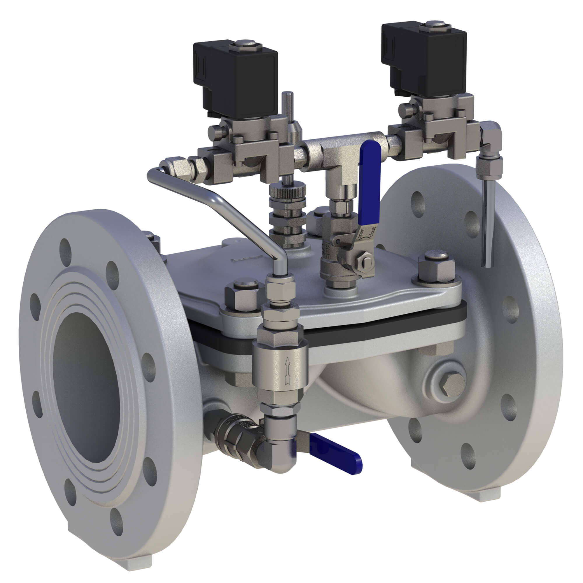
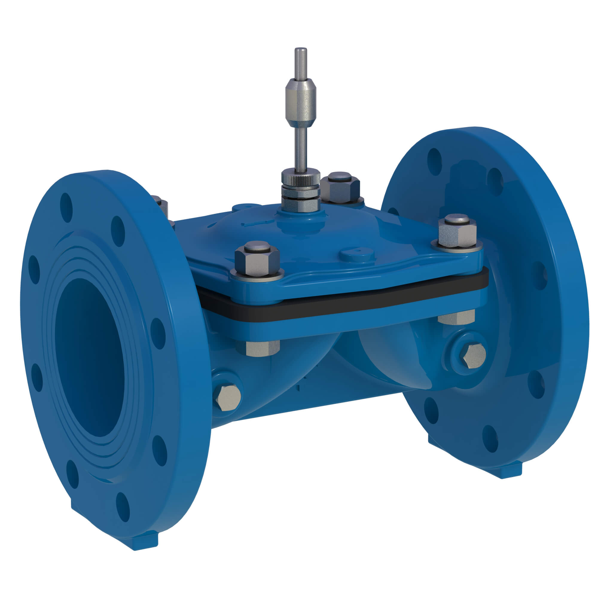
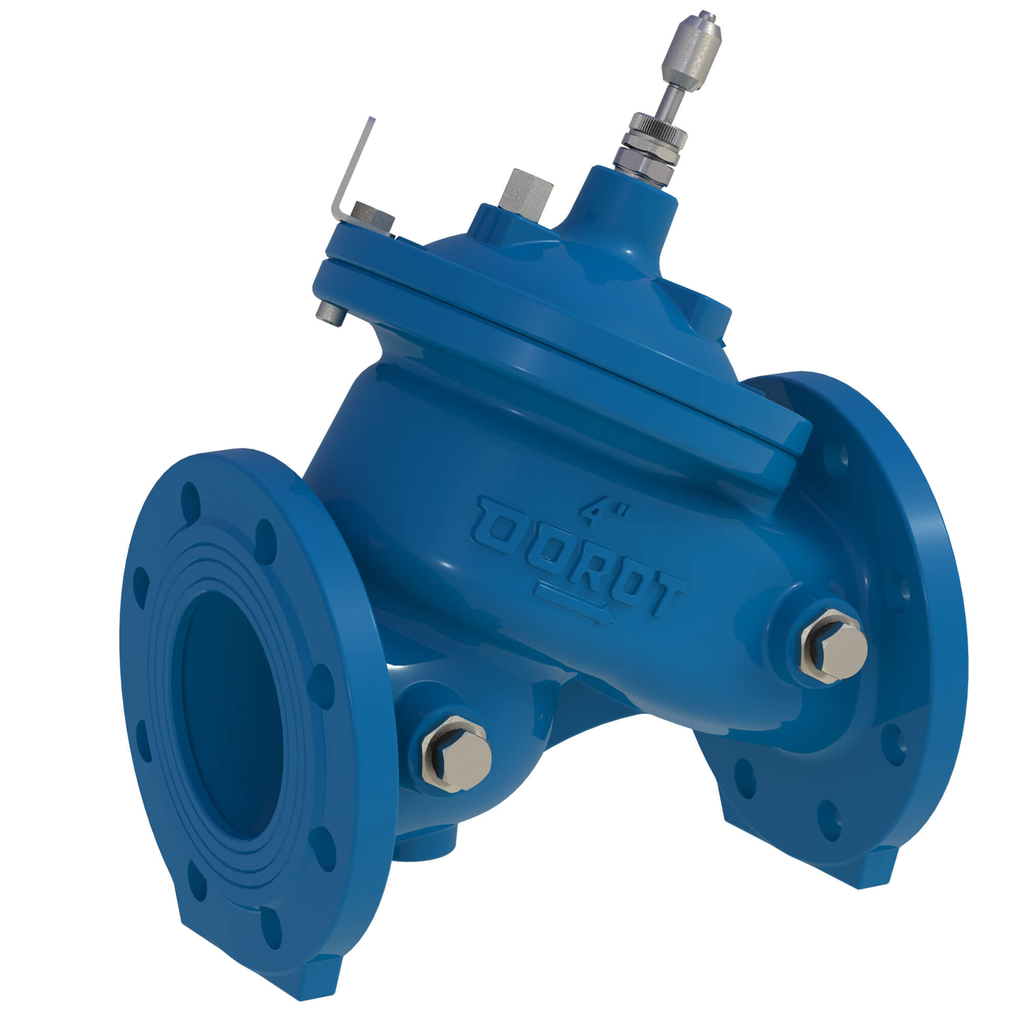
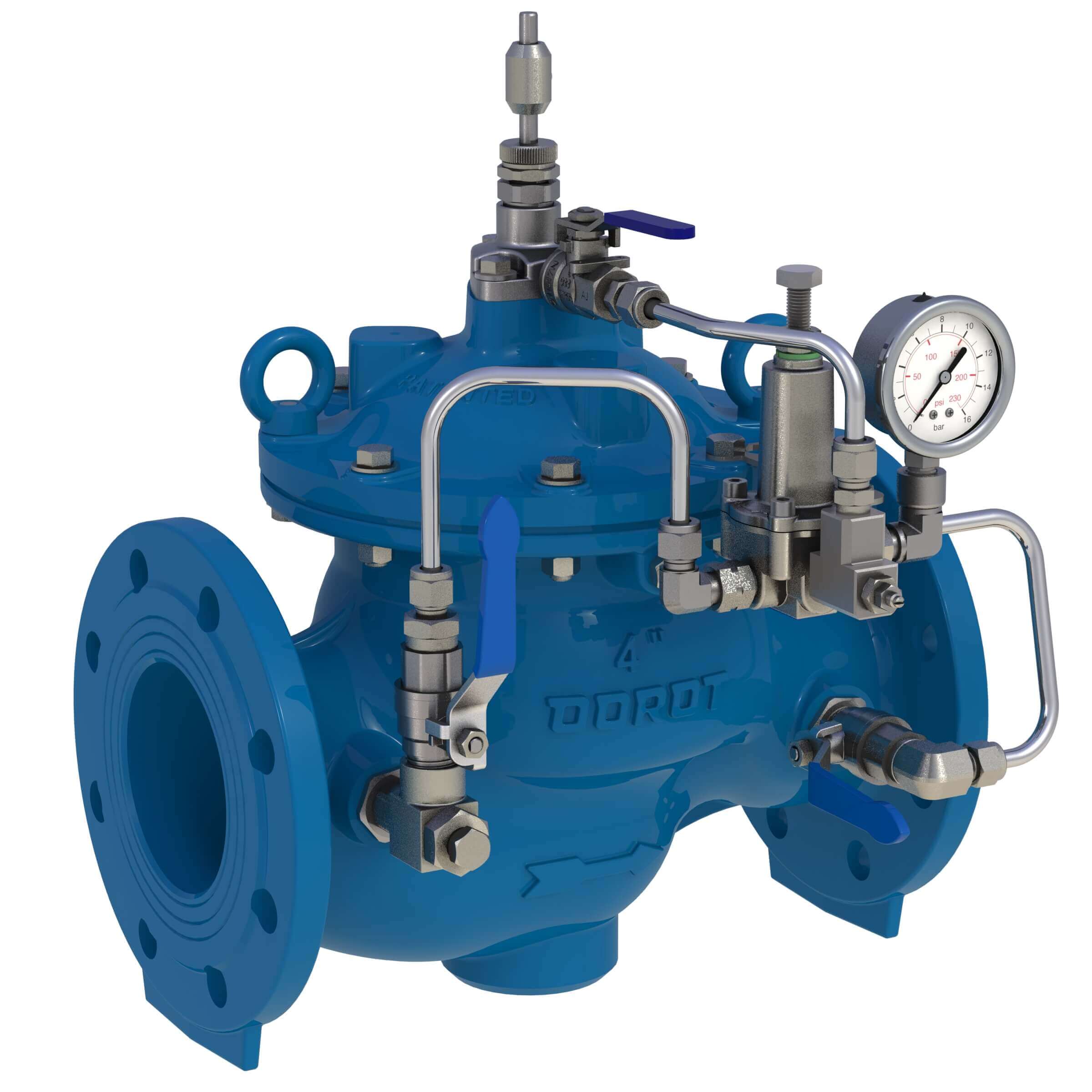
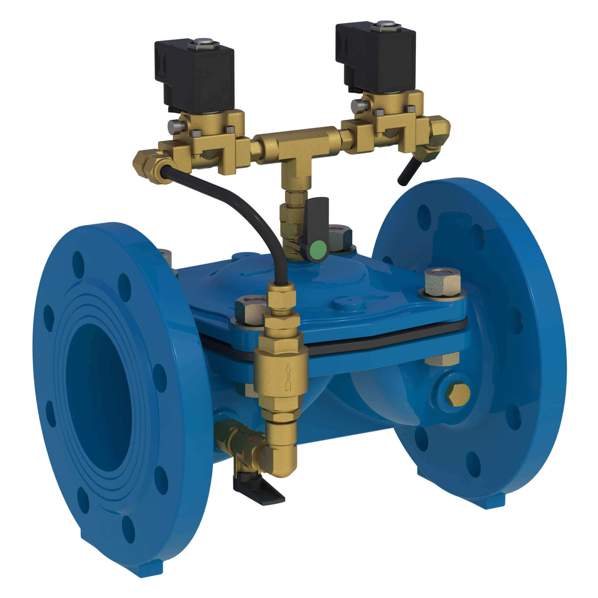
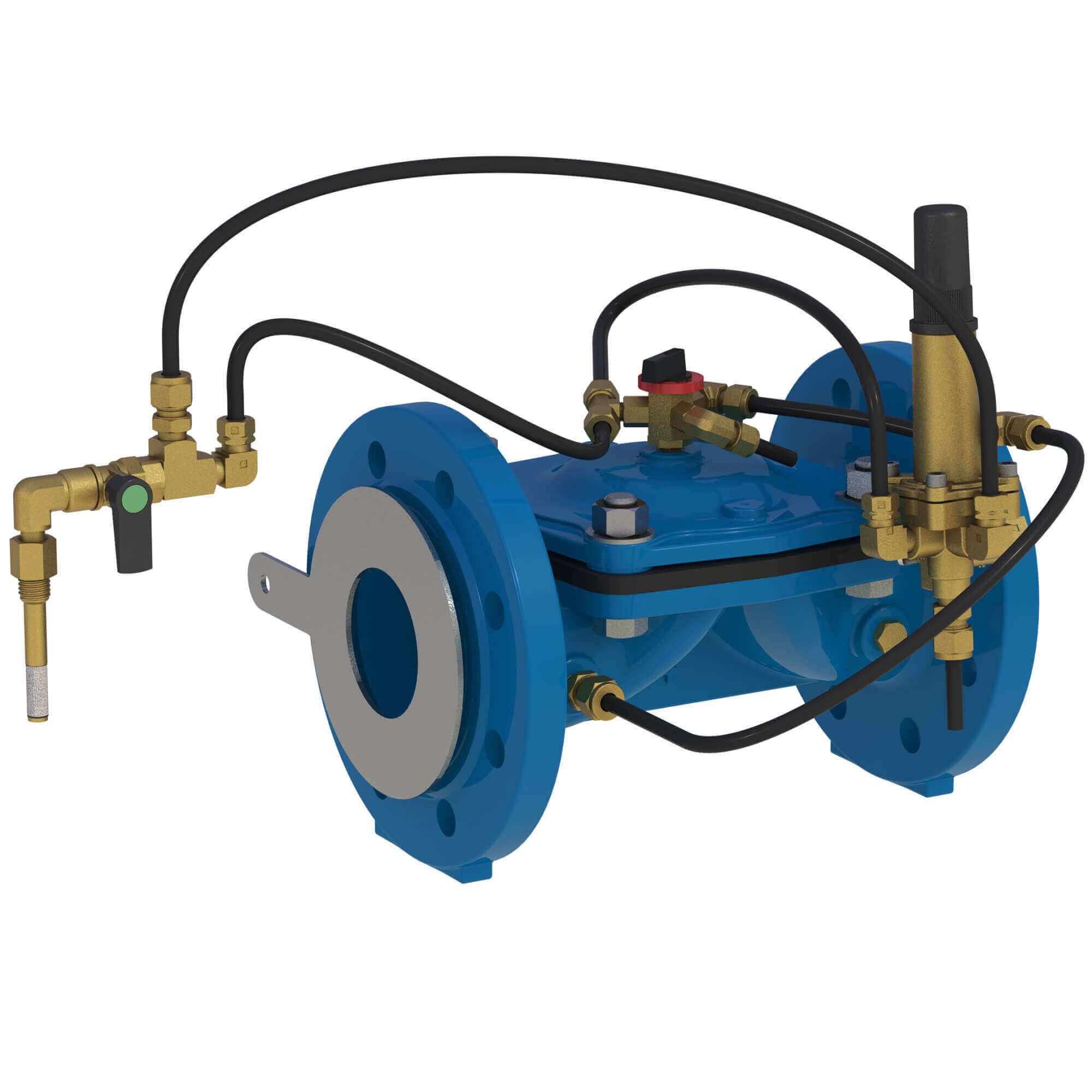
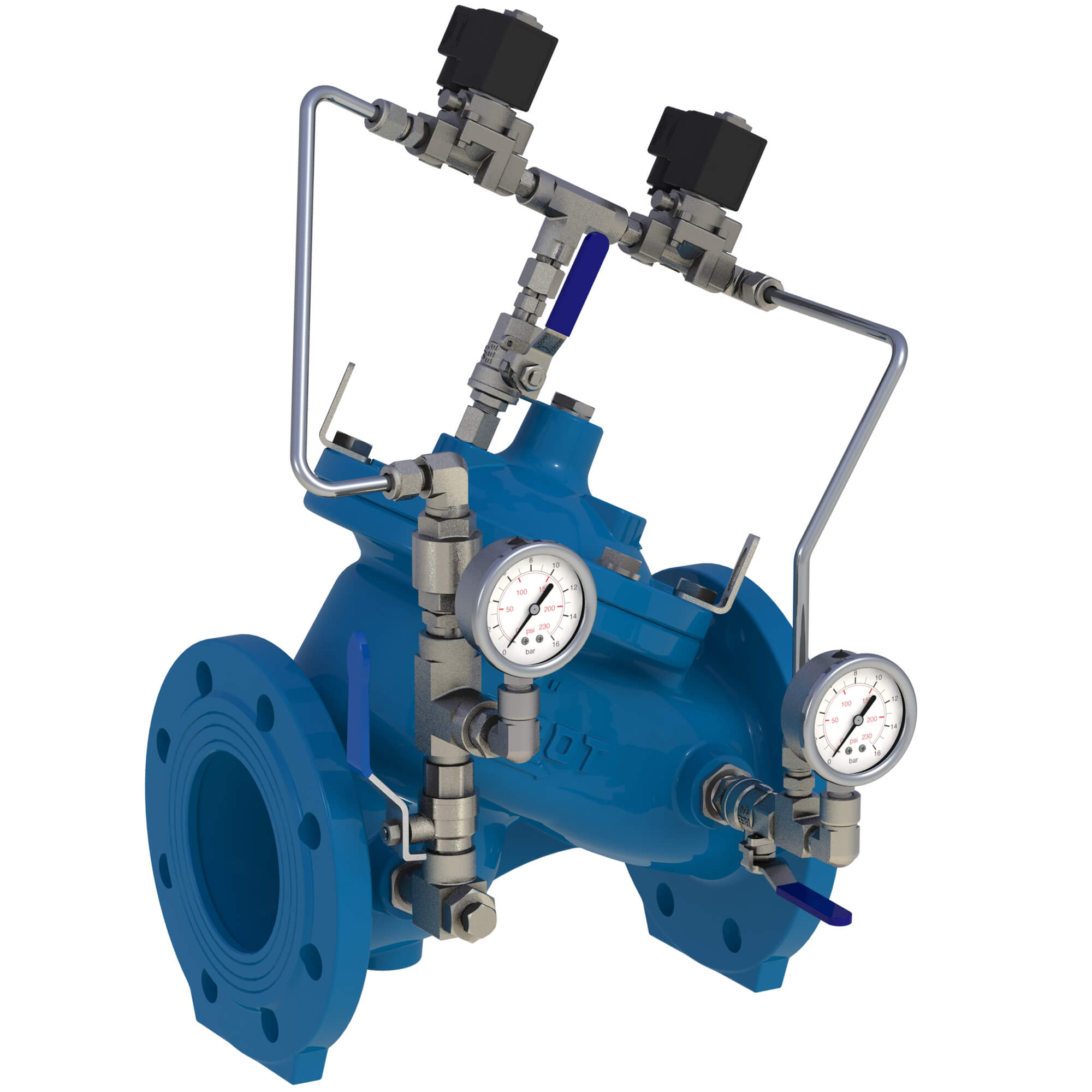
![Arisense Swg – DOROT S100 PS[R] (2W) WW](https://www.aquestia.com/wp-content/uploads/2024/12/WW-100-4-IS16RF-PSR2W-SS-EB_left.jpg)
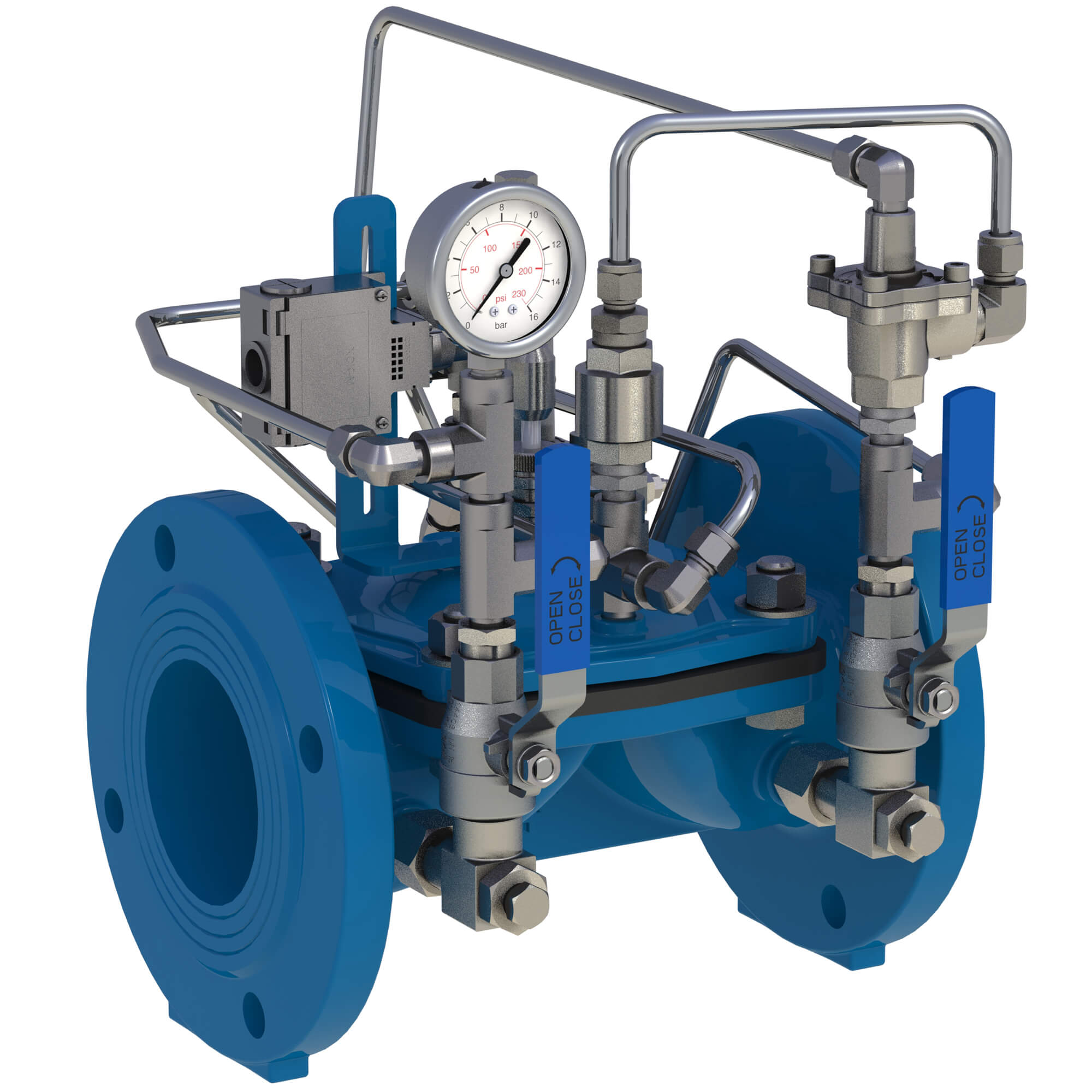
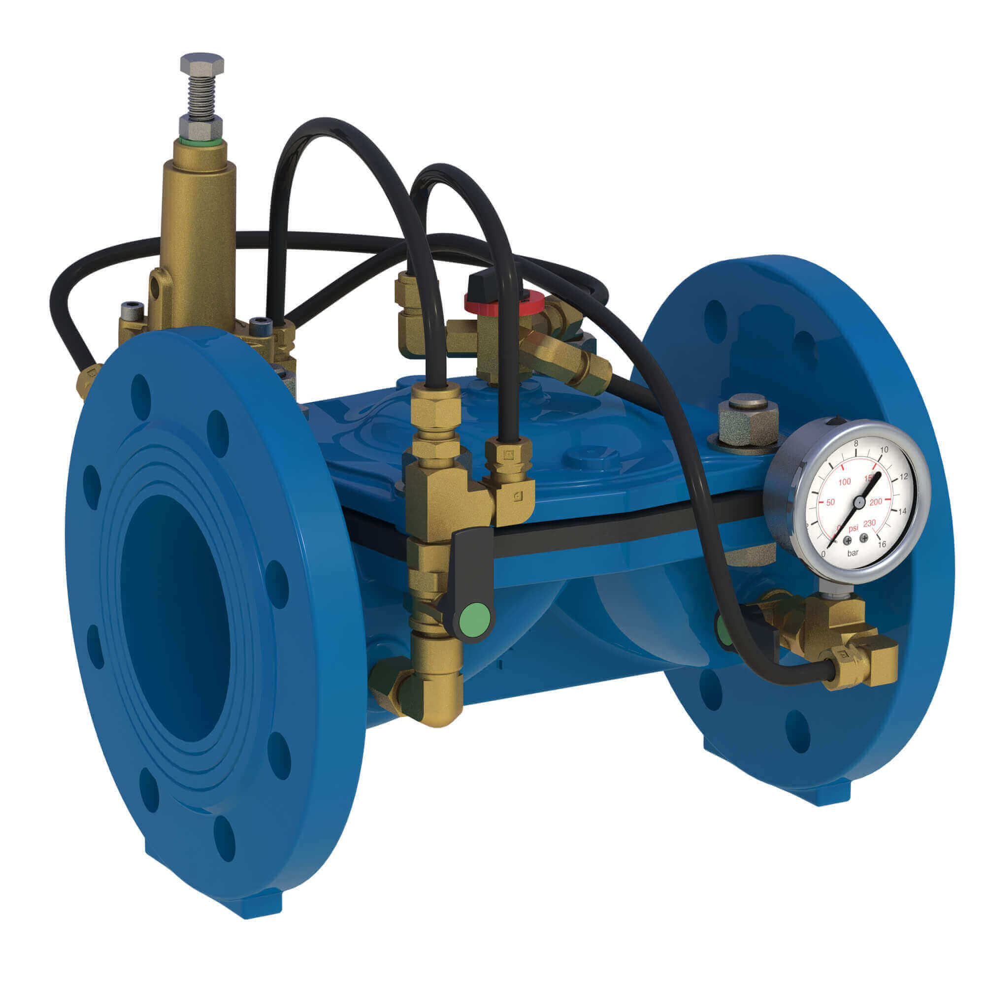
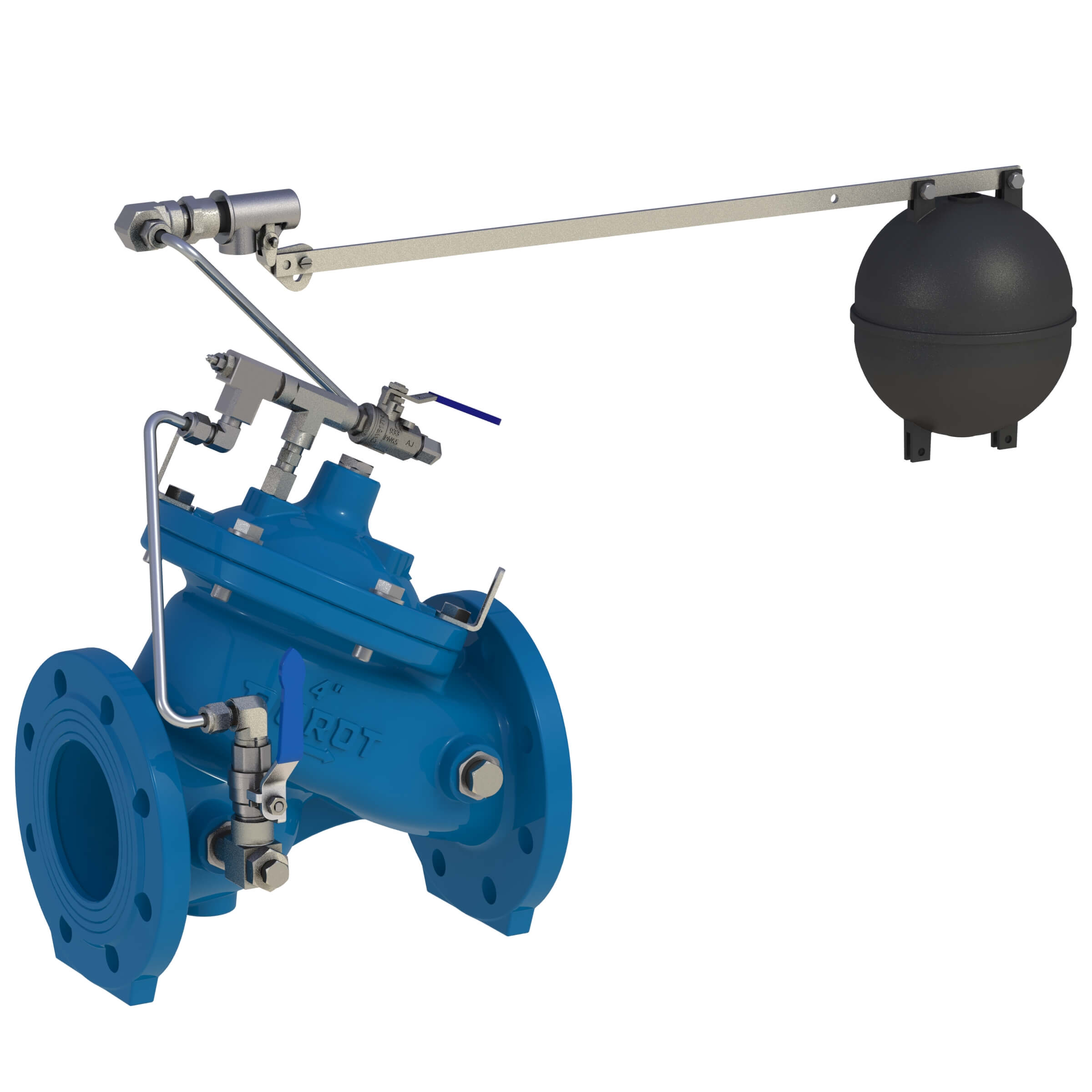
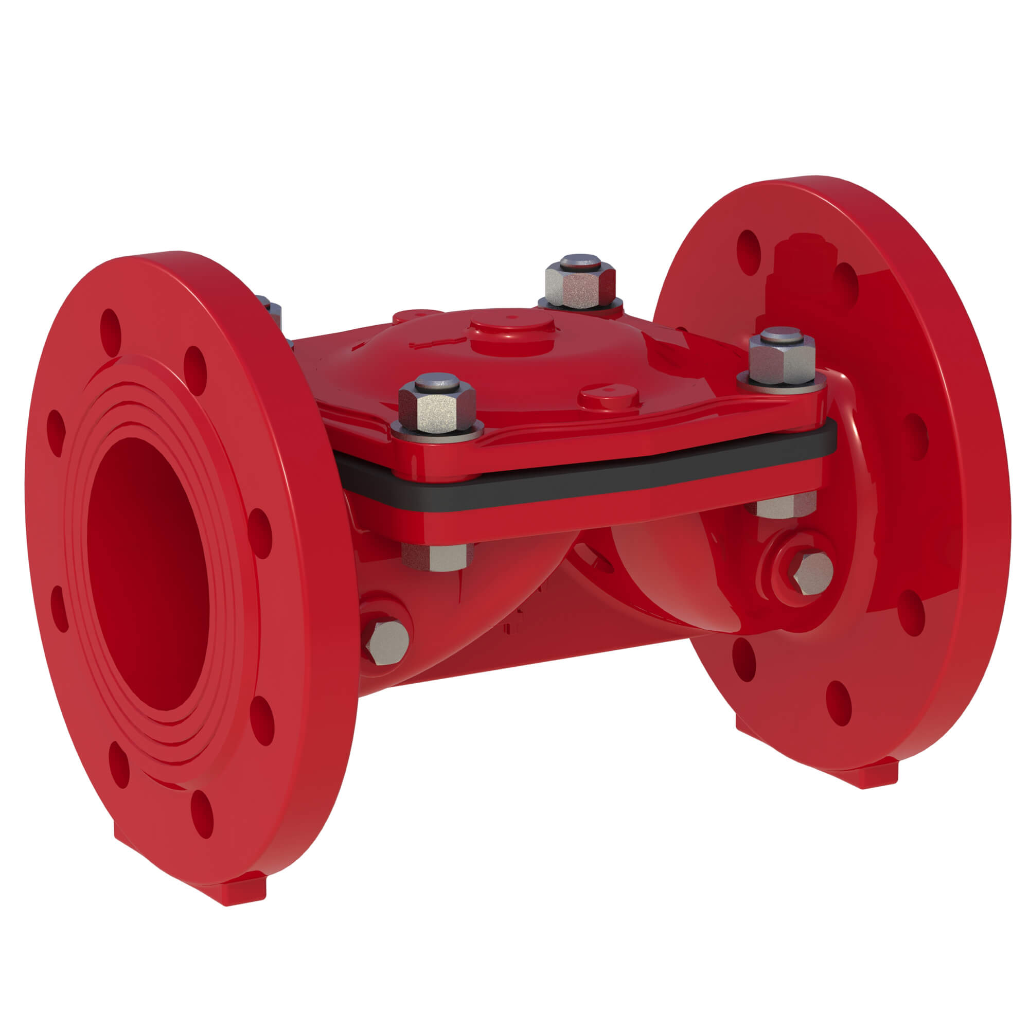
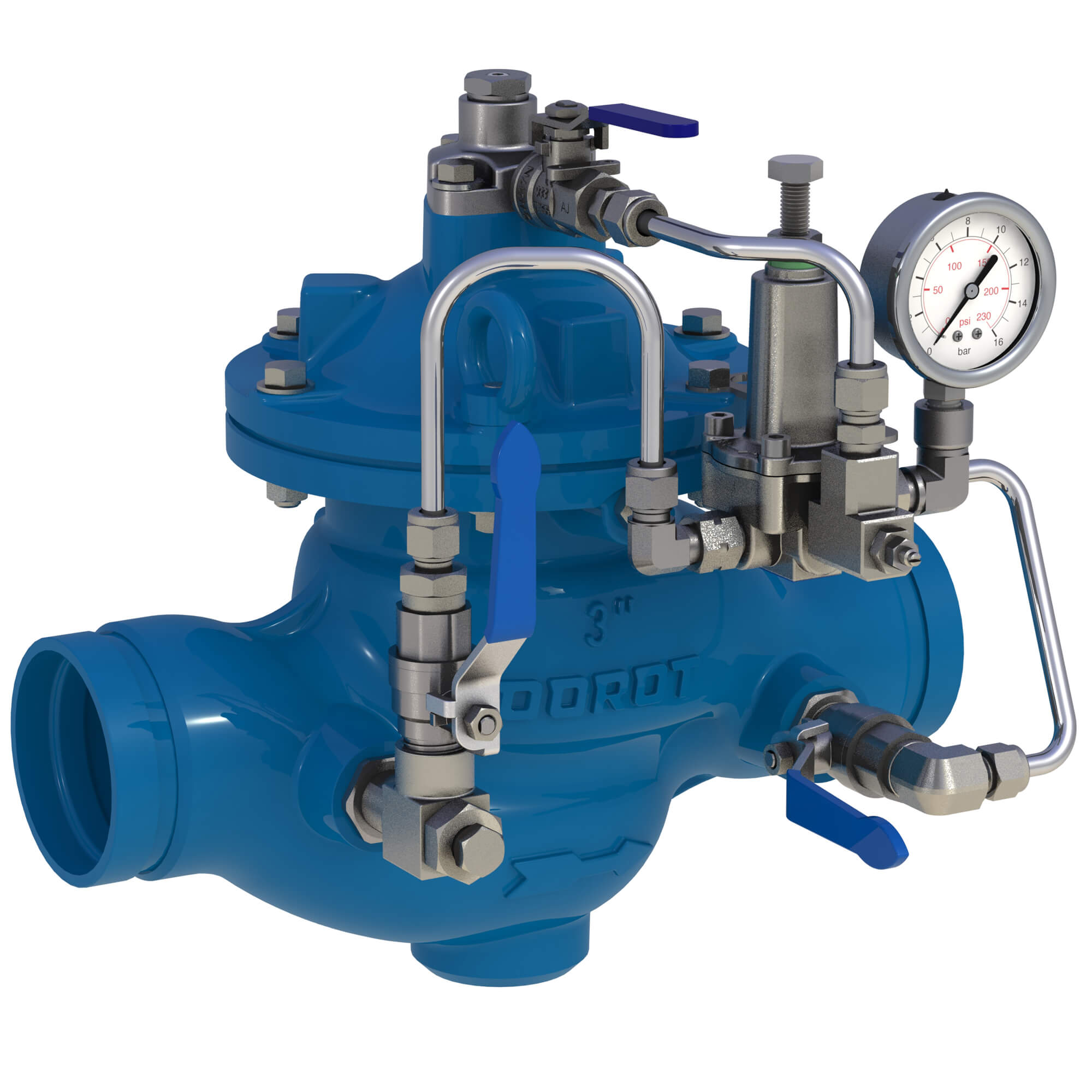
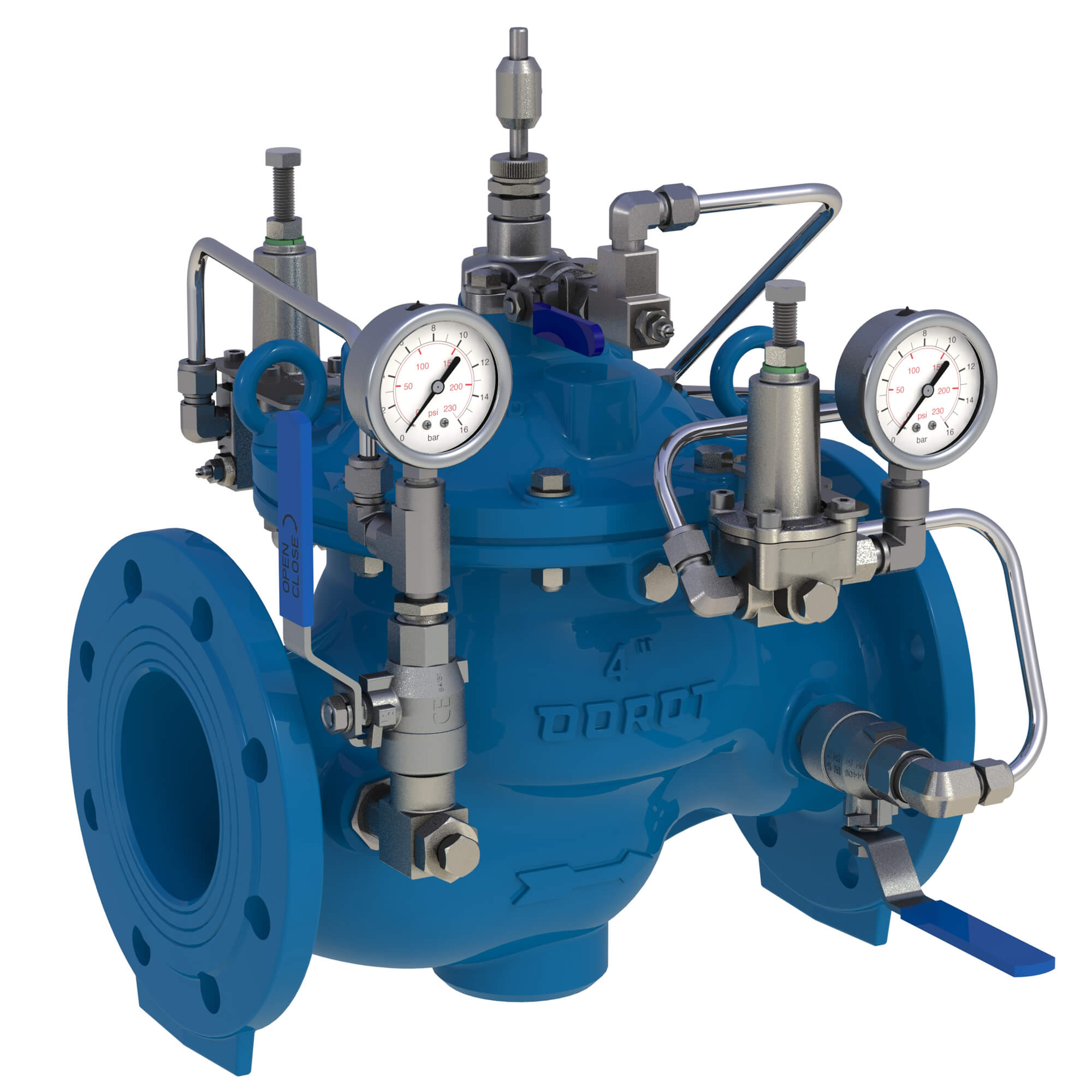
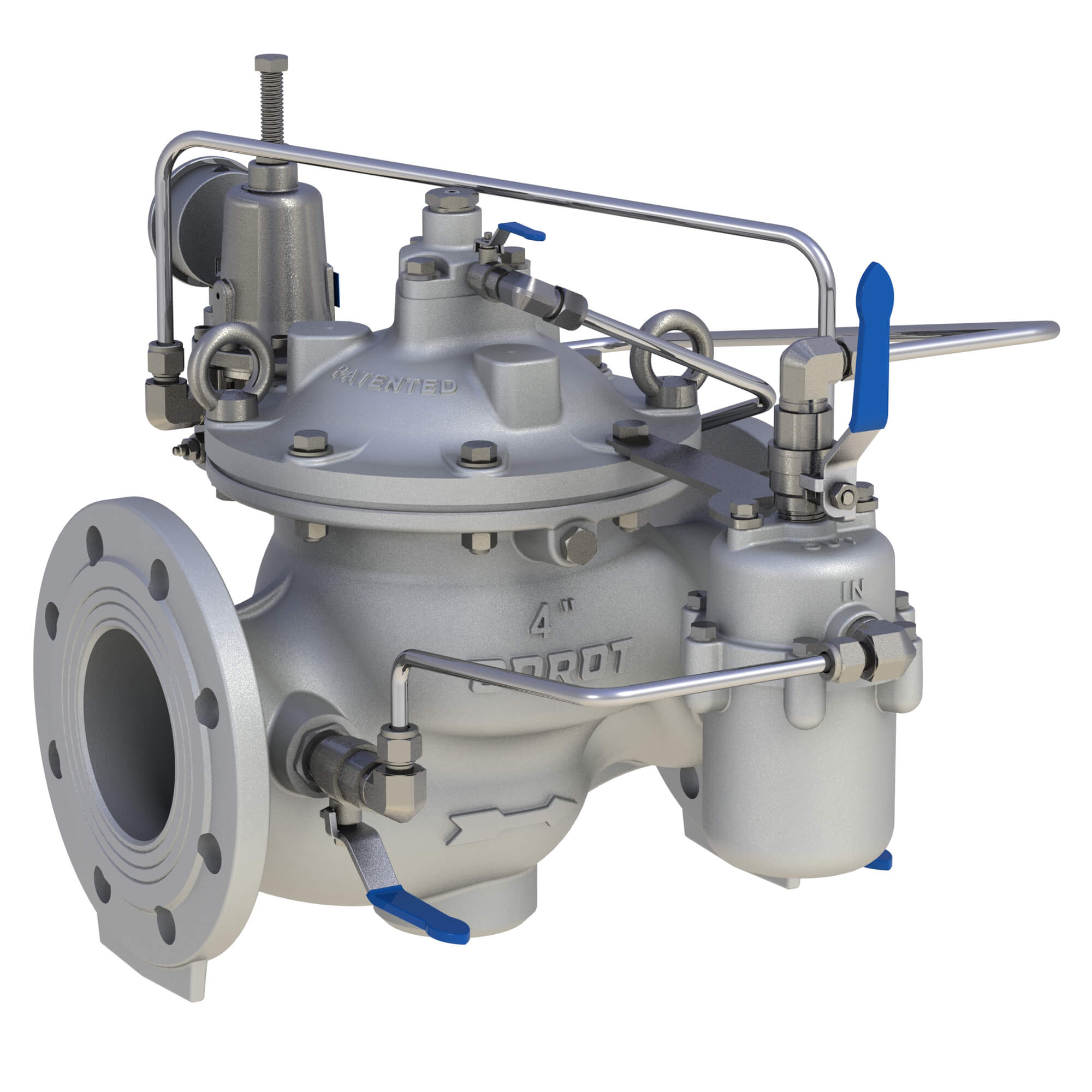
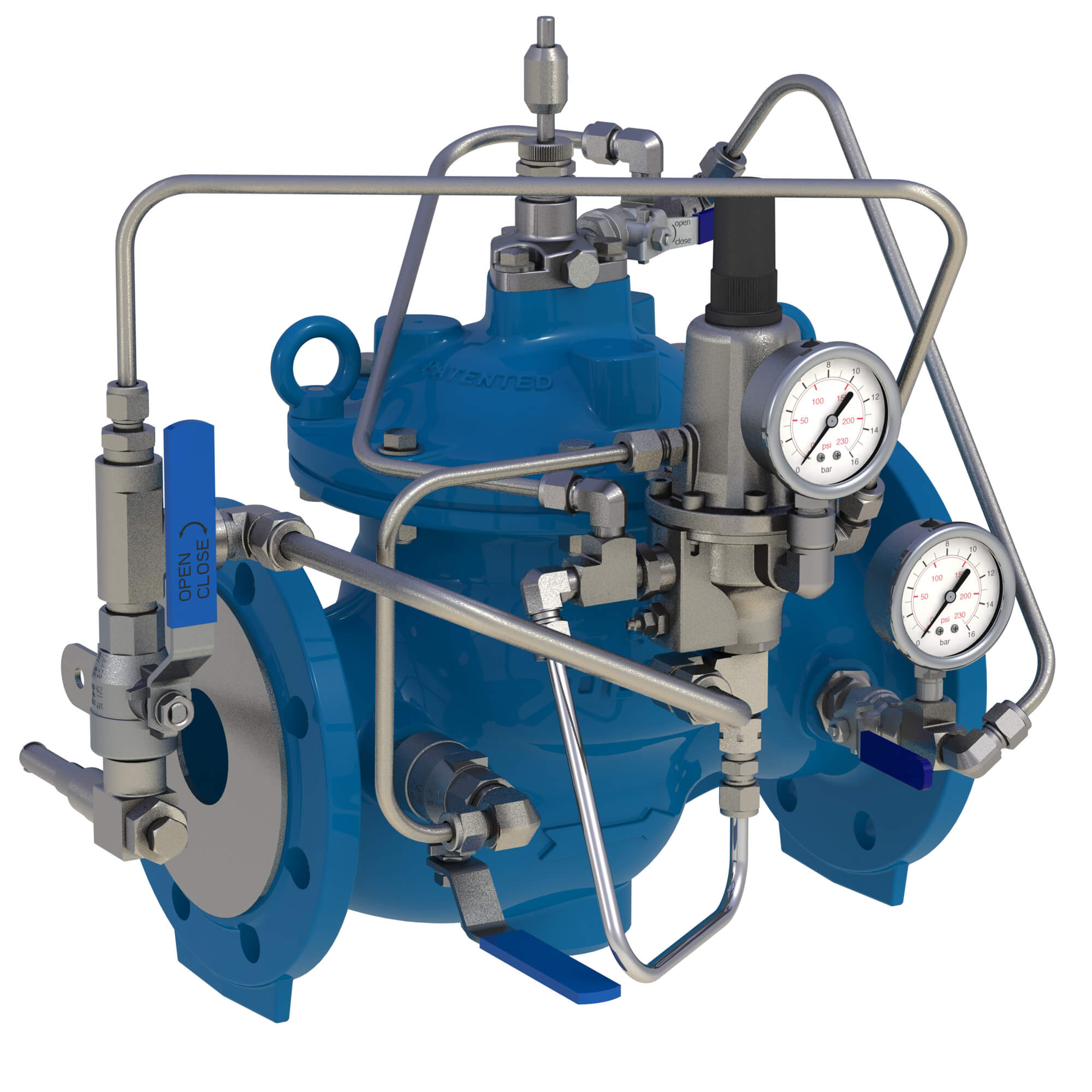
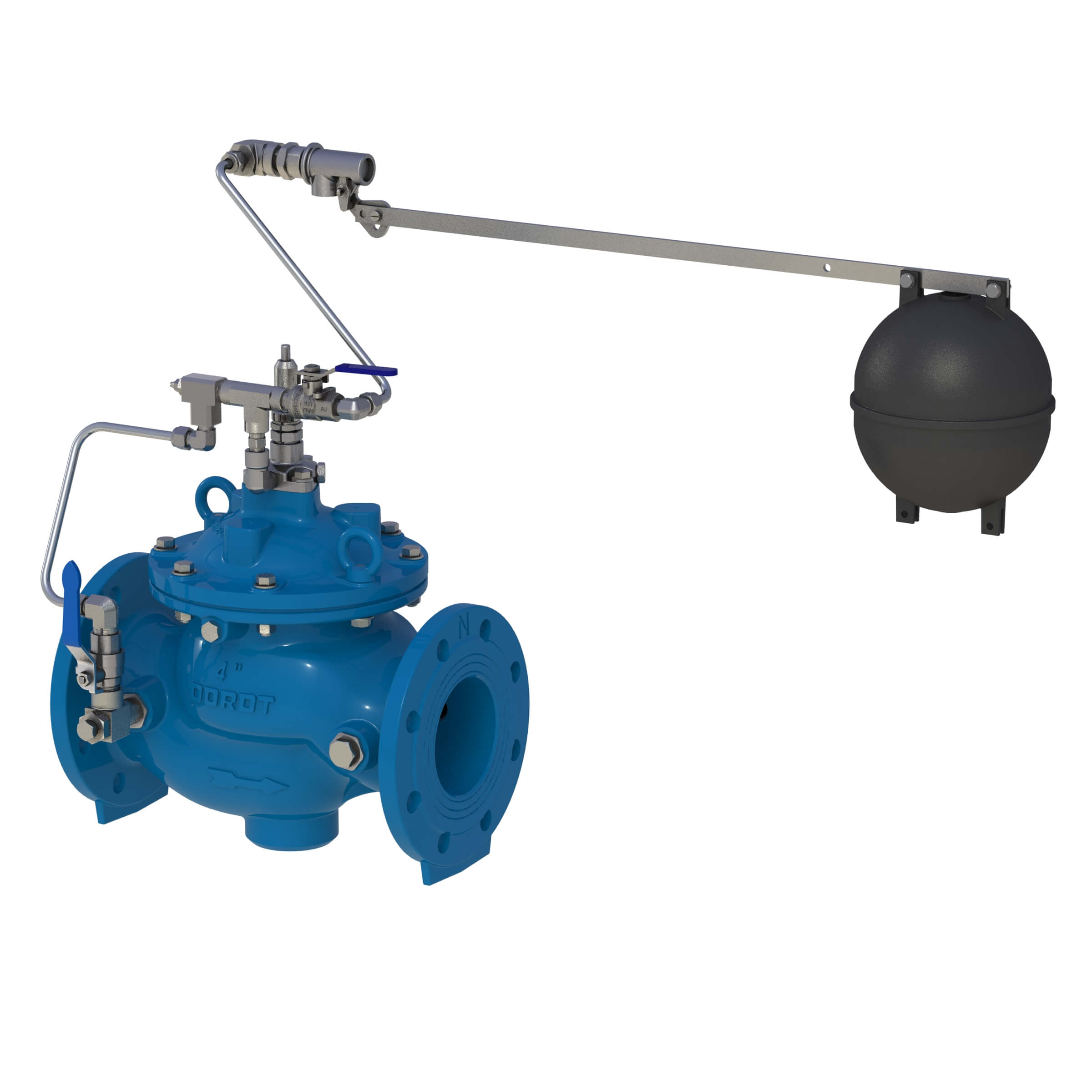
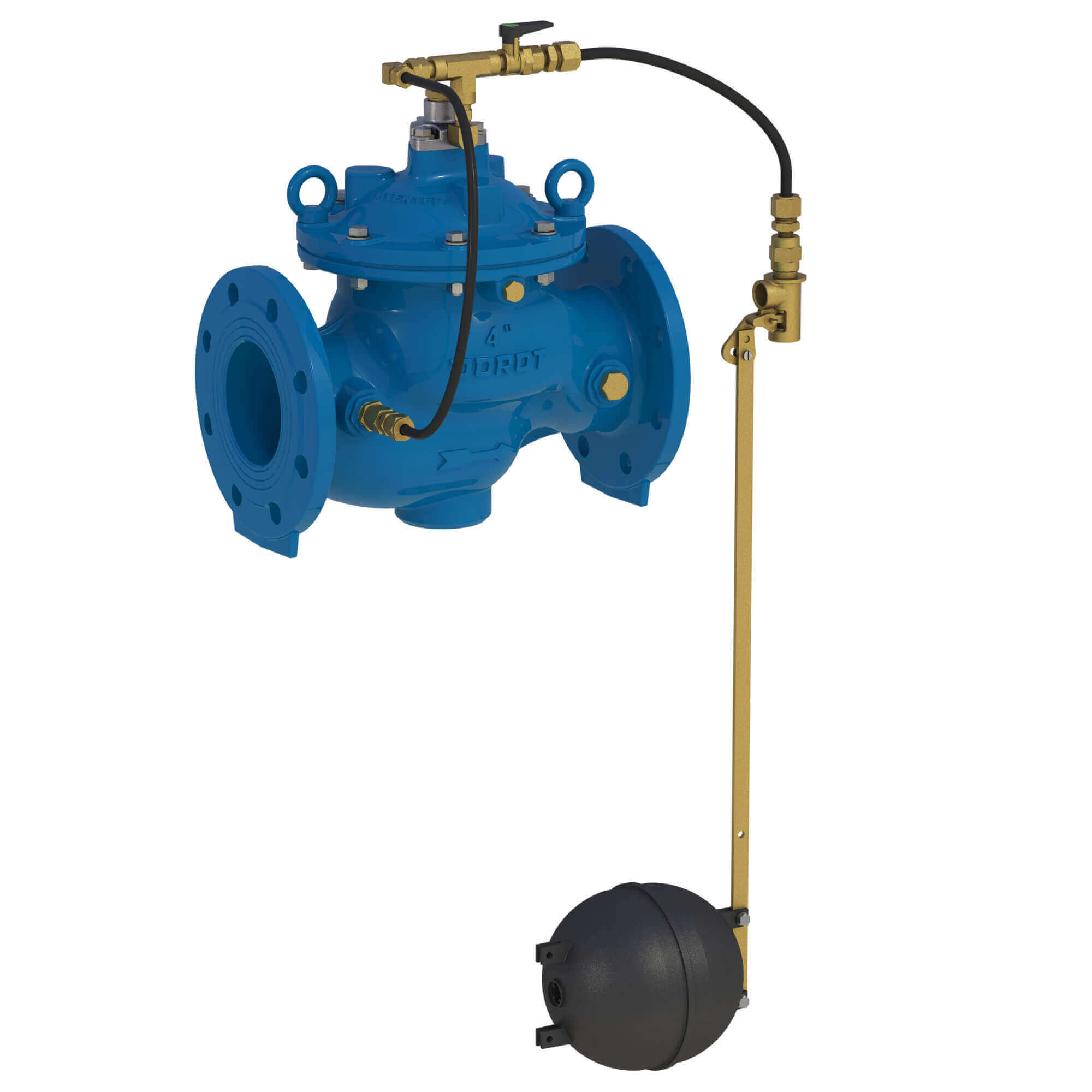
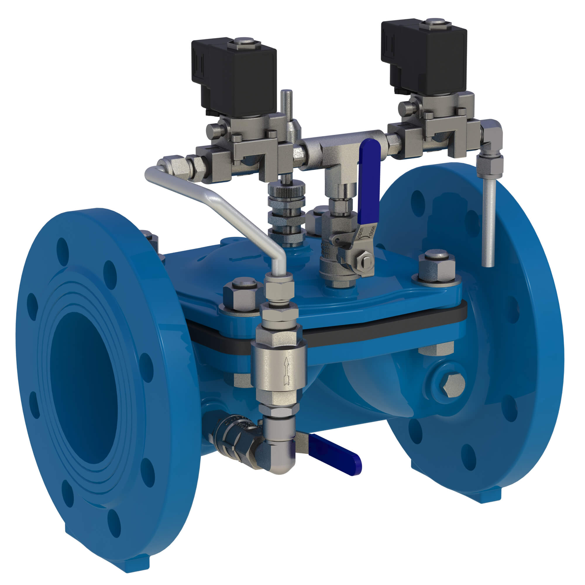
![Arisense Swg – DOROT S500 PS[R] (2W) WW](https://www.aquestia.com/wp-content/uploads/2024/12/WW-50-4-IS16RF-PSR2W-SS-EB_left.jpg)